
Spherical mechanism for quad-rotor amphibious robot

A robot and quadrotor technology, applied in the field of robots, can solve the problems of no integration of different motion modes, no consideration of robot protection, only applicable protection systems, etc., to achieve the effect of simple structure, practical function and low cost

Inactive Publication Date: 2015-07-22
HEFEI INSTITUTES OF PHYSICAL SCIENCE - CHINESE ACAD OF SCI +1
View PDF7 Cites 22 Cited by
  • Summary
  • Abstract
  • Description
  • Claims
  • Application Information

AI Technical Summary

Problems solved by technology

Limited by the way of movement, most of the currently developed mobile robots based on these ways of movement are only suitable for a single working environment
In recent years, a small number of amphibious and even amphibious robots have also appeared. For example, the invention patent of Publication No. 101954844A discloses an amphibious all-round mobile mechanism for water, land and air, but it superimposes omnidirectional wheels for the ground and rotors for flight. Together, the different motion modes are not really integrated into one, and the protection of the robot is not considered, which makes it easy to cause damage when the robot switches between different motion modes
Chinese utility model patent CN203680323U discloses a general-purpose multi-rotor robot backbone support safety protection system, but the protection system is only suitable for flying robots, and a spherical mechanism of a four-rotor amphibious robot proposed by the present invention is used as the movement device and protection of the amphibious robot. device, which is fundamentally different from the former

Method used


Image

  • Spherical mechanism for quad-rotor amphibious robot
  • Spherical mechanism for quad-rotor amphibious robot
  • Spherical mechanism for quad-rotor amphibious robot

Examples


Embodiment 1

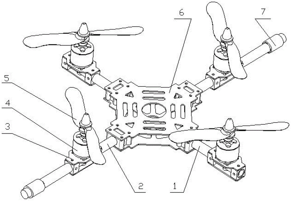
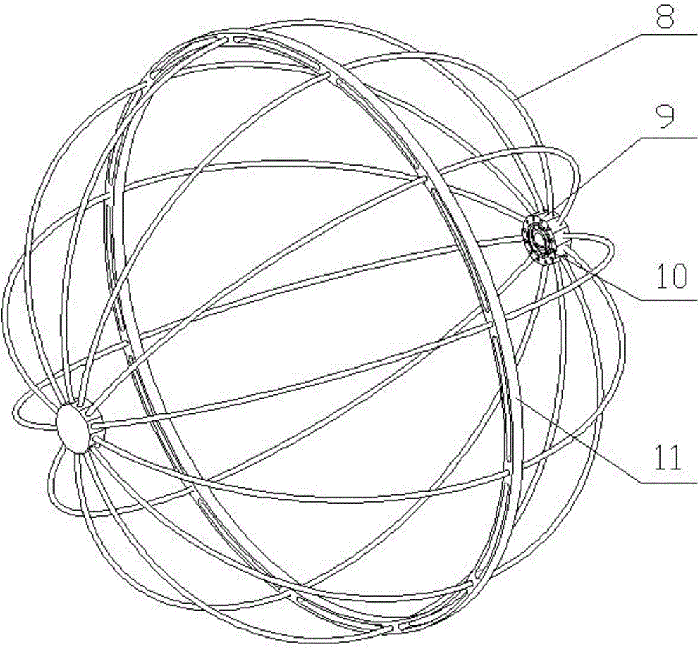
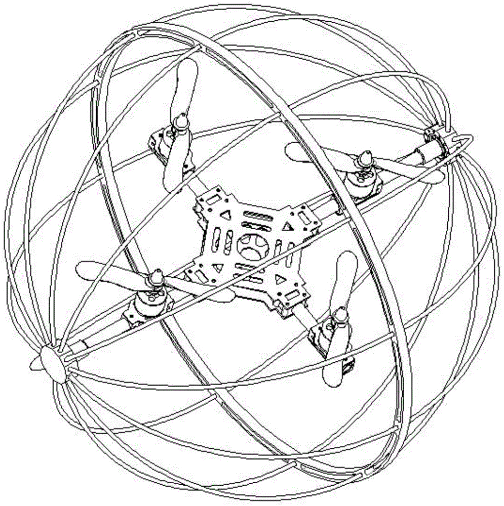
[0018] see Figure 1-Figure 4 , in an embodiment of the present invention, a spherical mechanism of a four-rotor amphibious robot mainly consists of a rotor mechanism and a spherical shell mechanism.

[0019] figure 1 It is the rotor mechanism in the spherical mechanism of the four-rotor amphibious robot of the present invention, mainly composed of a short axis 1, a long axis 2, a motor base 3, a motor 4, a rotor 5, a base 6 and a connecting shaft 7, the short axis 1 and the long axis 2 are perpendicular to each other and the axes are in the same plane, the intersection of the axes coincides with the center of the base 6, the motor base 3 is fixed on one side of the long axis 2, the motor 4 is fixed on the motor base 3, and the rotor 5 is fixed on the rotating shaft of the motor 4. The set of motor base-motor-rotor is evenly distributed on the short axis 1 and the long axis 2 around the base 6, and two connecting shafts 7 are installed at both ends of the long axis 2. The ba...


PUM


Abstract

The invention discloses a spherical mechanism for a quad-rotor amphibious robot. The spherical mechanism is composed of a rotor wing mechanism and a spherical shell mechanism, wherein the rotor wing mechanism is composed of a long shaft, a short shaft, a base, four rotor wings and four motors, the spherical shell mechanism is composed of a flexible rod, two fixed bases and a rolling ring, the long shaft is perpendicular to the short shaft, the axis of the long shaft and the axis of the short shaft are located on the same plane, the four rotor wings and the motors are symmetrically installed on the long shaft and the short shaft, and a connecting shaft on the long shaft is connected with the fixed bases of the spherical shell mechanism to enable the rotor wing mechanism to rotate around the long shaft relative to the spherical shell mechanism. The rotor wing mechanism provides power for the robot, and the robot is made to fly in the air or roll on the ground by setting the rotating speed and direction of the four rotor wings. When the robot flies in the air, the spherical shell mechanism serves as a protecting device. When the robot rolls on the ground, the spherical shell mechanism serves as a protecting device and a rolling device. The spherical mechanism has the advantages of being simple in structure, practical, convenient to dismantle, convenient to maintain, low in cost and the like.

Description

technical field [0001] The invention relates to the field of robots, in particular to a spherical mechanism of a four-rotor amphibious robot. Background technique [0002] Existing mobile robots have different motion modes, such as wheel type, leg type, peristaltic motion, and flight. Their motion performances have their own advantages, but there are also deficiencies, mainly in the limitation of environmental adaptation. Limited by the way of movement, most of the currently developed mobile robots based on these ways of movement are only suitable for a single working environment. In recent years, a small number of amphibious and even amphibious robots have also appeared. For example, the invention patent of Publication No. 101954844A discloses an amphibious all-round mobile mechanism for water, land and air, but it superimposes omnidirectional wheels for the ground and rotors for flight. At the same time, different motion modes are not really integrated into one, and the p...

Claims


Application Information

Patent Timeline
IPC IPC(8): B60F5/02B64C27/08
Inventor 李涛刘效骆敏舟陈赛旋付龙庄晓明魏强王美玲张丽华
Owner HEFEI INSTITUTES OF PHYSICAL SCIENCE - CHINESE ACAD OF SCI
Learn More