
Shaft extension for use with outboard bearing designs

a technology for outboard bearings and shafts, which is applied in the direction of positive displacement liquid engines, pumps, machines/engines, etc., can solve the problems of rubbing degrading performance, affecting the performance of electrically powered air, so as to achieve the effect of reducing performance or failur

Inactive Publication Date: 2002-07-16
WESTINGHOUSE AIR BRAKE TECH CORP
View PDF1 Cites 21 Cited by
  • Summary
  • Abstract
  • Description
  • Claims
  • Application Information

AI Technical Summary

Benefits of technology

Therefore, one objective of the invention is the provision of a shaft extension which will enable an existing electric motor driven air compressor to be retrofitted such that the end of the crankshaft of the air compressor terminates in an outboard rotational bearing, which provides considerable structural support to the crankshaft and considerably reduces the possibility that the air compressor will suffer decreased performance or failure due to the rotor and stator of the electric motor having become canted with respect to one another.
Another objective of the invention is the provision of such a shaft extension which is inexpensive to produce and reliable in operation.

Problems solved by technology

Such relative angular displacement between the rotor and stator can significantly degrade the performance of the electrically powered air compressor, and can even lead to failure of the combined system.
Such rubbing degrades performance.
Over time in service, these forces can lead to the rubbing described above and, ultimately, can result in the above-described shorting and burning out of the electric motor 18.
Such precise machining of the previously separate bearing plate 16 and stator frame 22 is an expensive procedure, and is not always entirely satisfactory in its implementation.

Method used


Image

  • Shaft extension for use with outboard bearing designs
  • Shaft extension for use with outboard bearing designs
  • Shaft extension for use with outboard bearing designs

Examples


Embodiment Construction

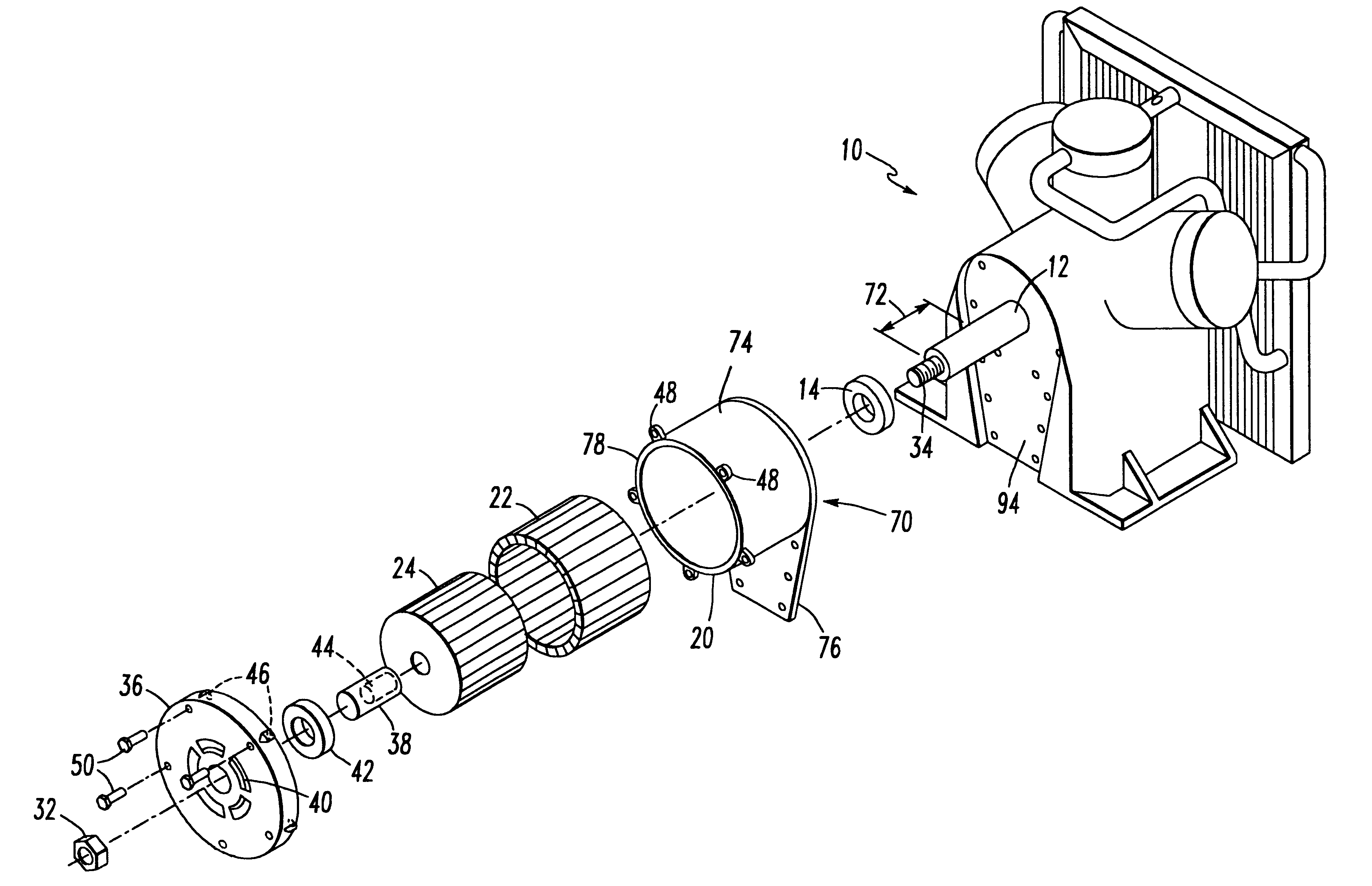
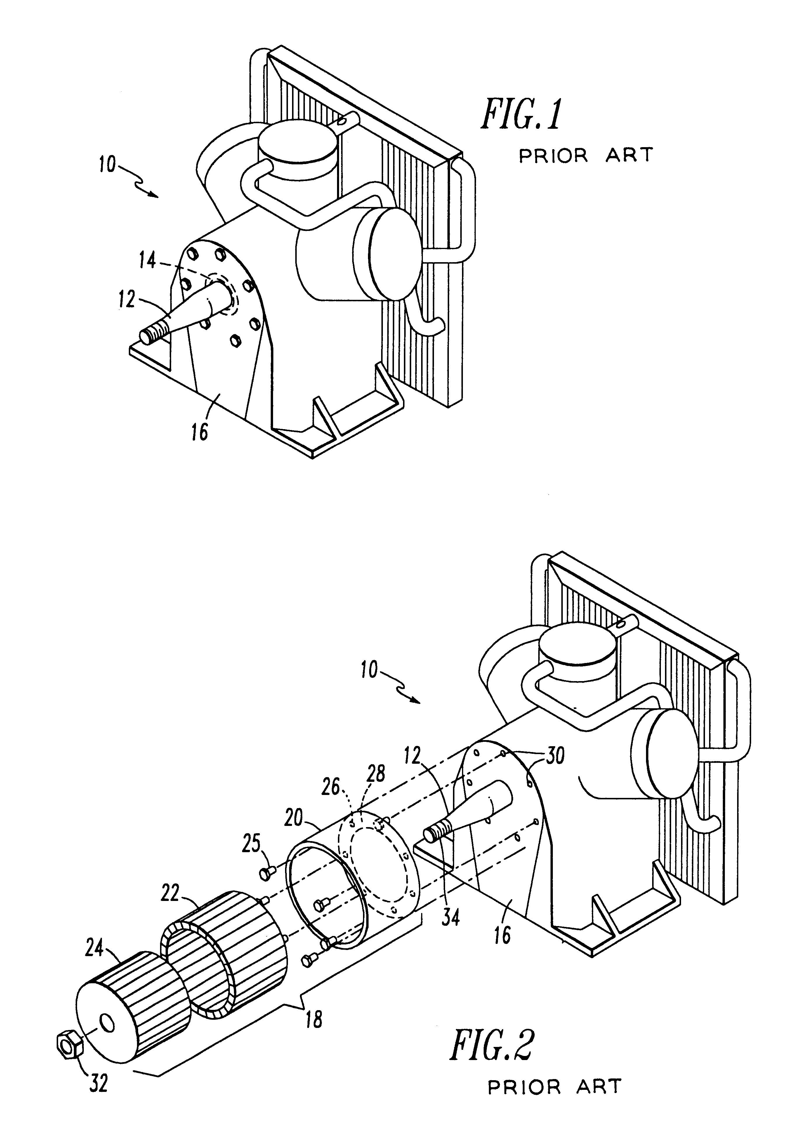
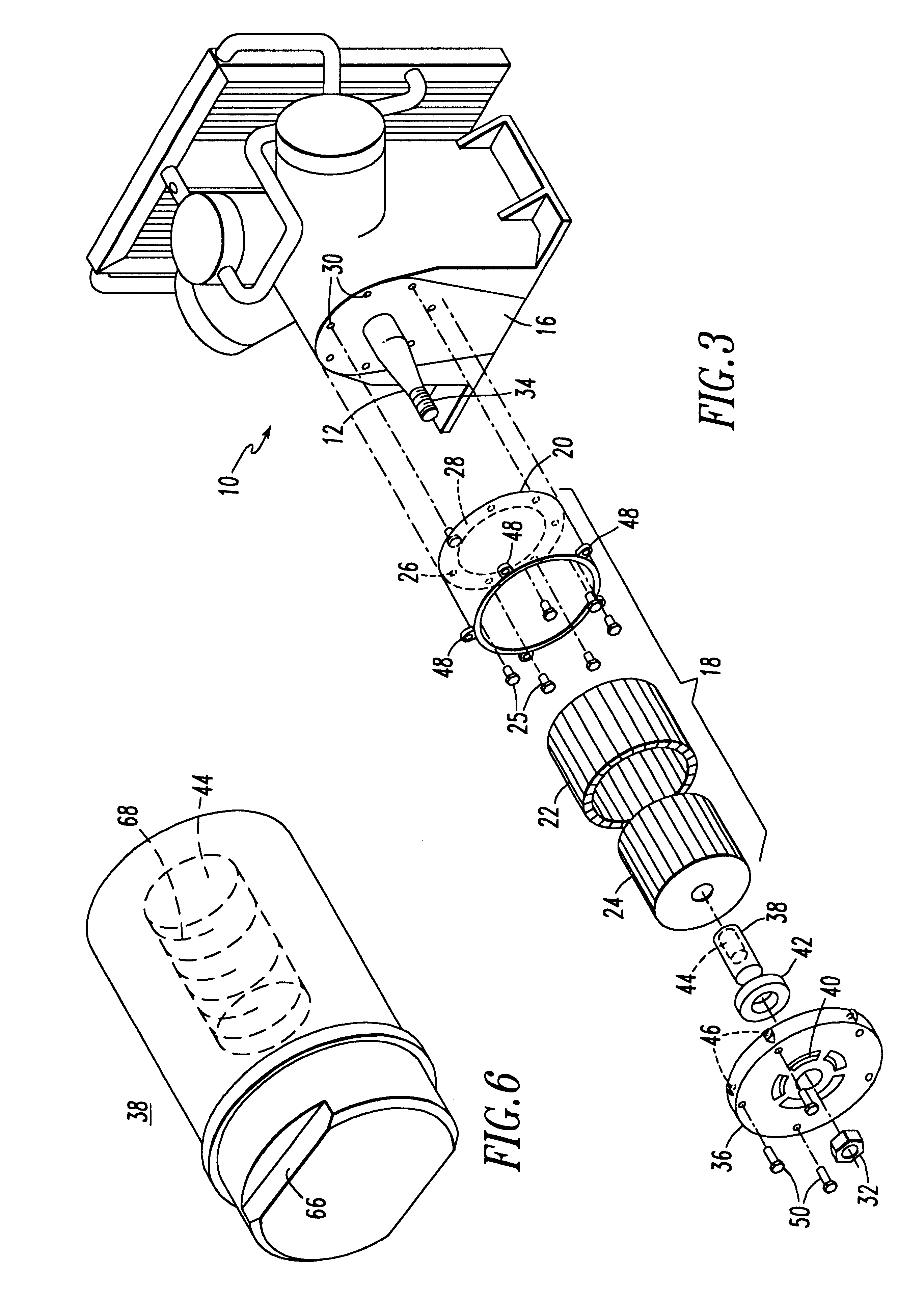
Referring now to FIG. 3, an apparatus (or "kit") for retrofitting the air compressor 10 with a third or outboard bearing generally includes an endplate 36 and a shaft extension 38. The stator frame 20 is cantilevered from the exposed outboard face of the bearing plate 16 of the air compressor 10 through any suitable means. For example, the stator frame 20 may be secured to the bearing plate 16 through the use of the bolts 25 which pass through the holes 26 formed in the inwardly extending radial lip 28 formed on the rear (i.e., inward) face of the stator frame 20, the bolts 25 terminating in the threaded blind holes 30 formed in the bearing plate 16.

The endplate 36 includes a bearing housing 40, which provides a mounting for a third or outboard bearing 42. The stator 22 is fixedly mounted to the stator frame 20, and the rotor 24 is fixedly mounted to the crankshaft 12, for example, in the conventional manner as described above.

The shaft extension 38 is of general cylindrical shape a...


PUM


Abstract

A shaft extension for attachment to a crankshaft of an electric motor driven air compressor to axially extend the crankshaft for engagement with an outboard rotational bearing. The electric motor driven air compressor includes a bearing plate, an inboard rotational bearing mounted on the bearing plate, the crankshaft projecting through both of the inboard rotational bearing and the bearing plate and terminating in a distal end disposed exterior of the bearing plate. The air compressor also includes an electric motor, the electric motor having a stator frame, a stator fixedly mounted within the stator frame, and a rotor fixedly mounted to the crankshaft for rotation therewith and disposed interior of the stator. The air compressor further includes the outboard rotational bearing disposed axially outboard of the stator frame, the stator, and the rotor. The shaft extension includes an extension member having an extended major axis and a minor axis extending substantially transverse to the extended major axis and a connection mechanism for connecting the extension member to the distal end of the crankshaft.

Description

The present invention relates, in general, to an air compressor that is powered by an electrical motor.More particularly, the present invention relates to an air compressor, driven by an electrical motor, which is used to supply compressed air to the air brake system of a railed vehicle (e.g., a train or light rail vehicle).Even more particularly, the present invention relates to a shaft extension which enables an air compressor that supplies compressed air for a braking system and that is driven by an electrical motor to be retrofitted such that the outboard end of the crankshaft of the compressor is supported by a "third" or "outboard" bearing. As explained fully below, the provision and use of such a "third" or "outboard" bearing significantly reduces the possibility that the rotor of the electrical motor will "cant" with respect to the stator of the electrical motor. Such relative angular displacement between the rotor and stator can significantly degrade the performance of the ...

Claims


Application Information

Patent Timeline
IPC IPC(8): F04B35/00F04B39/14F04B35/04F04B39/00F04B25/00H02K7/00H02K7/14
CPCF04B25/00F04B35/04F04B39/0094F04B39/14
Inventor GOETTEL, WALTER E.DRUMMOND, ROGERSHAFFER, RONALDVARNEY, JAMESCUNKELMAN, BRIAN L.
Owner WESTINGHOUSE AIR BRAKE TECH CORP
Learn More