Rotary hydraulic actuator with hydraulically controlled position limits

a hydraulic actuator and position limit technology, applied in the direction of machines/engines, rotary/oscillating piston pump components, liquid fuel engines, etc., can solve the problems of adding complexity, weight, cost, etc., to the basic actuator devi

Active Publication Date: 2014-05-20
GENERAL ELECTRIC CO
View PDF44 Cites 21 Cited by
  • Summary
  • Abstract
  • Description
  • Claims
  • Application Information

AI Technical Summary

Problems solved by technology

While mechanical pitch stops are effective, they add complexity, weight, and cost to the basic actuator device.

Method used


Image

  • Rotary hydraulic actuator with hydraulically controlled position limits
  • Rotary hydraulic actuator with hydraulically controlled position limits
  • Rotary hydraulic actuator with hydraulically controlled position limits

Examples


Embodiment Construction

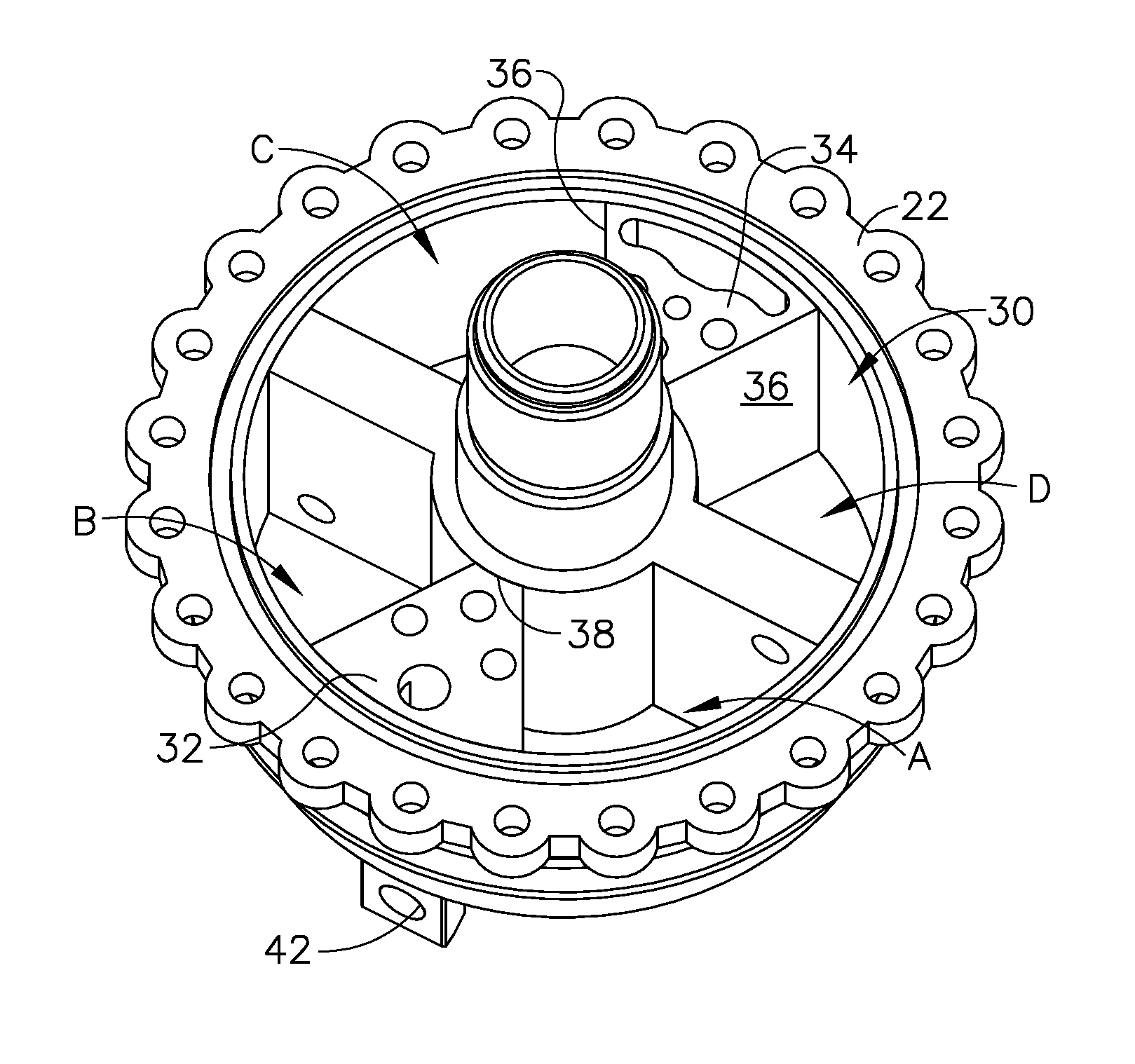
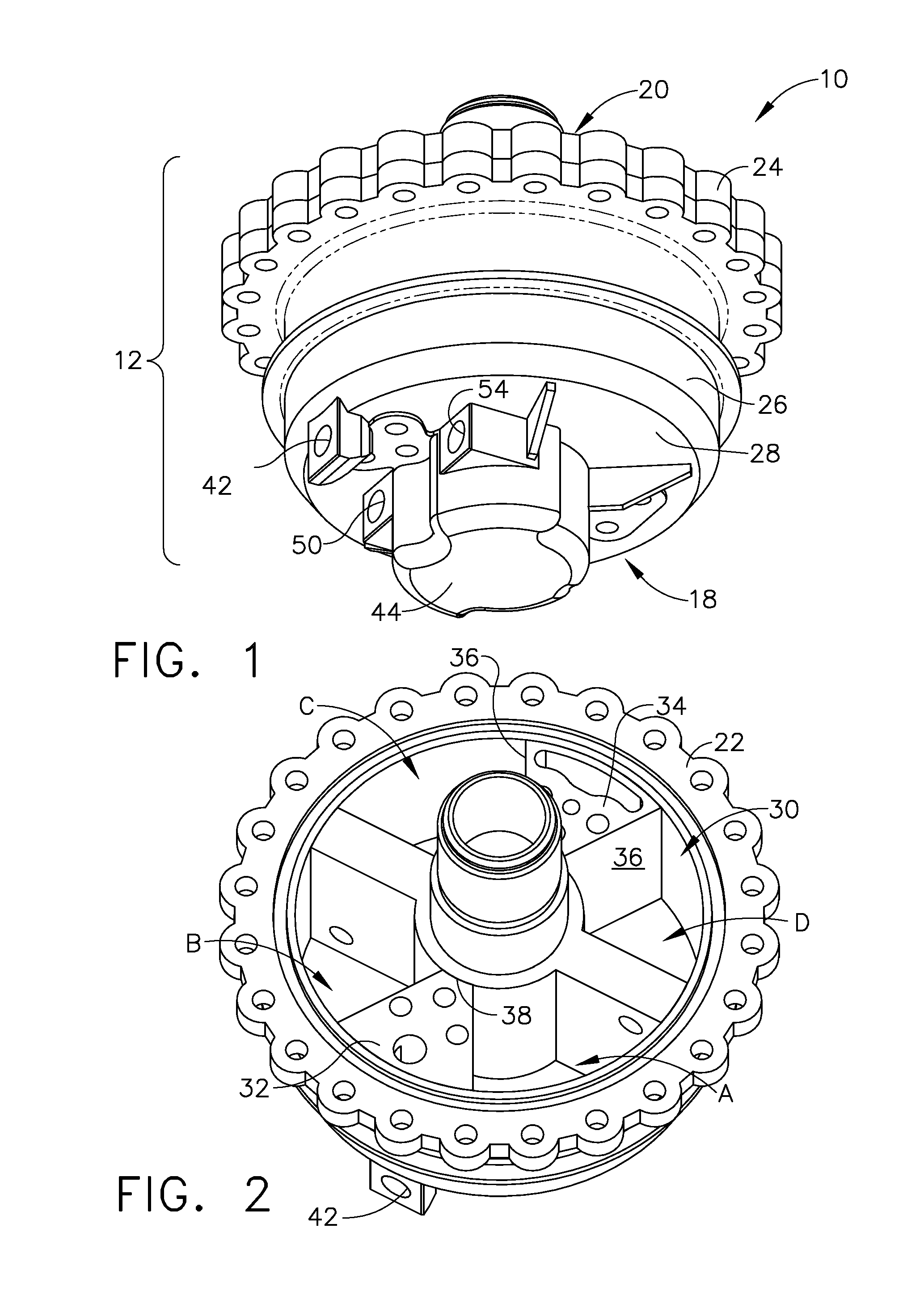
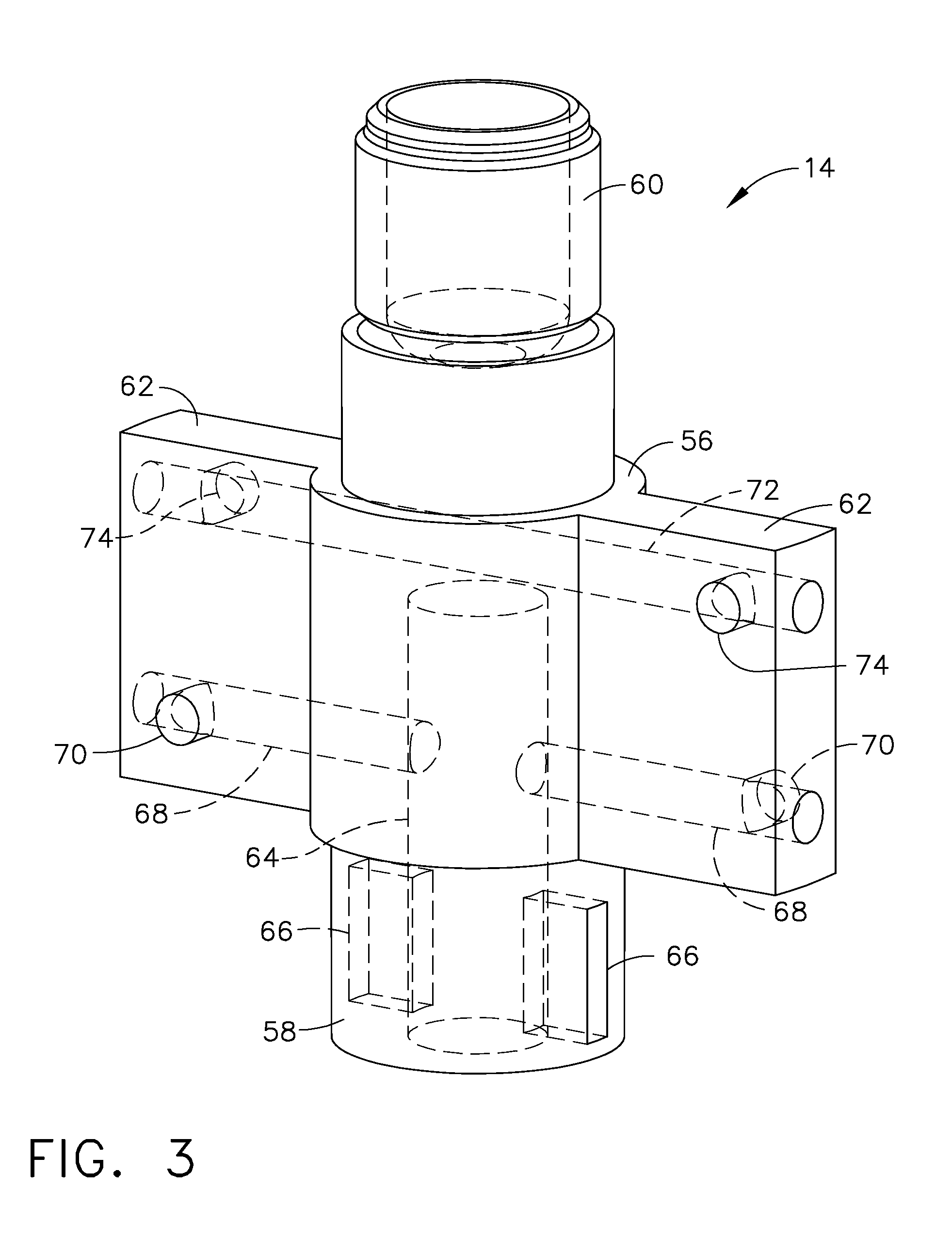
[0020]Referring to the drawings wherein identical reference numerals denote the same elements throughout the various views, FIGS. 1 and 2 depict a rotary hydraulic actuator 10 constructed according to the invention. The major components of the actuator 10 are a housing 12 and a rotor 14. As described in more detail below, the actuator 10 is operable to produce controlled rotary motion of the rotor 14 when the actuator 10 is provided with a flow of pressurized hydraulic fluid to its various ports. While it may be used for any mechanical load that requires rotary motion, the actuator 10 is particularly useful for controlling the pitch angle of an airfoil, such as gas turbine engine fan blade or a propeller blade (not shown).

[0021]The housing 12 has an inboard end 18 and an outboard end 20, and is assembled from a base 22 and a cover 24 which are assembled to each other by bolts or other suitable fasteners. The housing 12 has a peripheral wall 26 and an end wall 28 which cooperatively ...


PUM


Abstract

A rotary hydraulic actuator includes a housing defining a chamber, a first boss, and a port block with a bore communicating with the chamber. The port block includes rotor supply and drain ports communicating with the bore, and a stator port communicating with the chamber through a stator hole in the boss. A rotor mounted in the internal chamber includes: a body with a laterally-extending arm; a first stub shaft received in the bore, the first stub shaft including base slots passing laterally therethrough; a first rotor port disposed in the arm in communication with the internal chamber, and oriented in a tangential direction relative to an axis of rotation; and internal passages which interconnect the rotor base slots and the first rotor port. Passages in the port block communicate with the bore and interconnect the rotor supply and drain ports at a first angular position of the rotor.

Description

BACKGROUND OF THE INVENTION[0001]This invention relates generally to hydraulic actuators and more particularly to motion control for such actuators.[0002]Aircraft powerplants are typically used to drive thrust-generating airfoil elements such as propellers or fan blades. It is known to vary the angle of incidence (i.e. “pitch angle”) of the airfoil elements relative to the rotating hub carrying them, in order to provide the maximum possible propulsive efficiency at various flight conditions.[0003]A common method of pitch control employs a hydraulic actuator which changes the blade pitch angle in response to pressurized fluid flow. The actuator may move the blade through pitch angles from “coarse” to “fine” and may also provide pitch angles suitable for ground operation. For safety reasons, it is important to limit the blade pitch angle during flight. This avoids overspeeding the powerplant, or imposing excessive structural loads or unexpected yawing moments to the aircraft. A typica...

Claims


Application Information

Patent Timeline
Patent Type & Authority Patents(United States)
IPC IPC(8): F01C9/00
CPCB64C11/385F15B15/12
Inventor GLYNN, CHRISTOPHER CHARLESZATORSKI, DAREK TOMDINSMORE, NICHOLAS ROWEMILLER, BRANDON WAYNE
Owner GENERAL ELECTRIC CO
Why Eureka
Try Eureka