Warning system with vibration and lane deviation prevention system with the warning system for automotive vehicle

a technology of warning system and warning system, which is applied in the direction of braking system, pedestrian/occupant safety arrangement, instruments, etc., can solve the problems of increasing the cost of the system, driving difficulty in immediately recognizing the tendency of lane deviation of the vehicle,

Active Publication Date: 2006-04-25
NISSAN MOTOR CO LTD
View PDF7 Cites 14 Cited by
  • Summary
  • Abstract
  • Description
  • Claims
  • Application Information

AI Technical Summary

Benefits of technology

[0004]Accordingly, it is an object of the present invention to provide a warning system with vibration and a lane deviation prevention system with the warning system that are capable of immediately and assuredly informing or warning a driver of a potential lane deviation, based on a driving condition of the vehicle with a minimum cost up.

Problems solved by technology

With only the artificial noise resembling the noise that is actually generated in passing on the rumble strip, a driver has difficulty in immediately recognizing a tendency of lane deviation of the vehicle in some cases, such as a case of the state that the driver has fallen asleep.
This leads to an increase in the cost of the system.

Method used


Image

  • Warning system with vibration and lane deviation prevention system with the warning system for automotive vehicle
  • Warning system with vibration and lane deviation prevention system with the warning system for automotive vehicle
  • Warning system with vibration and lane deviation prevention system with the warning system for automotive vehicle

Examples


first embodiment

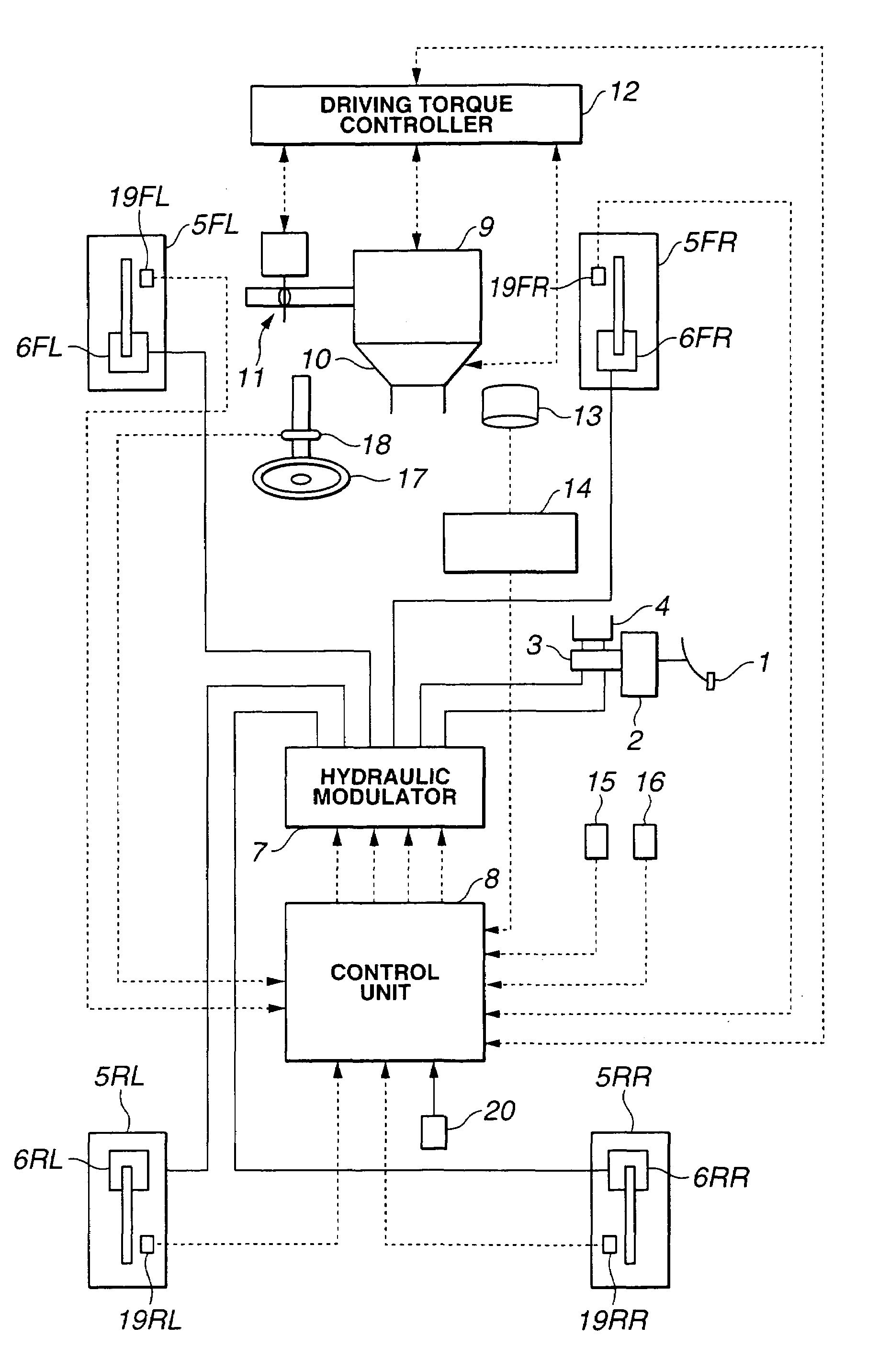
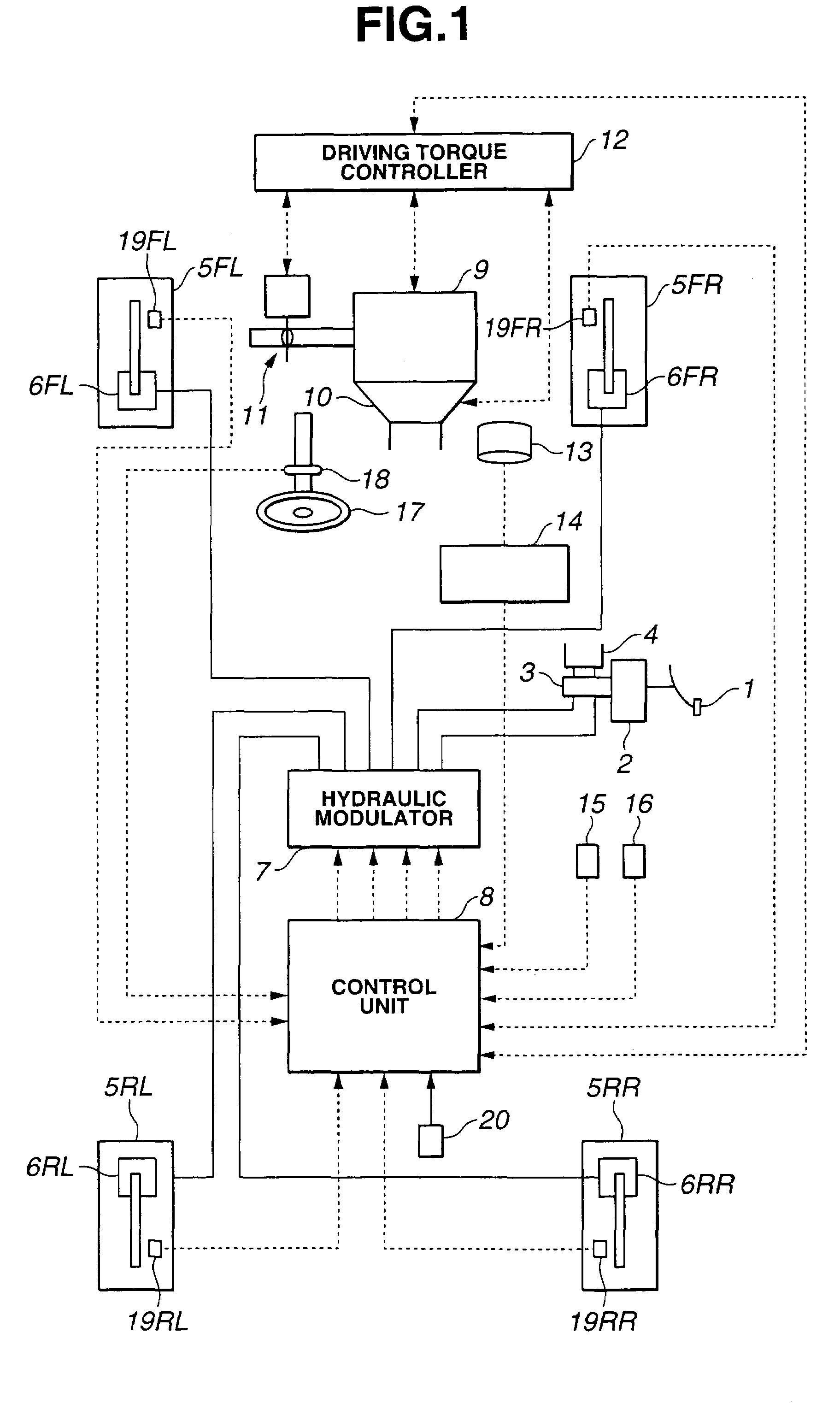
[0028]Referring now to FIG. 1, there is shown a rear drive automotive vehicle of the present invention. When a brake pedal 1 is depressed, hydraulic brake pressure in a master cylinder 3, which is connected to a brake fluid reservoir 4, is generated according to the depression of brake pedal 1 via a brake booster 2. The hydraulic brake pressure is supplied to wheel brake cylinders 6FL through 6RR each provided at road wheels5FL through 5RR.

[0029]A hydraulic modulator 7, which is adapted to be applied to hydraulic control systems such as an anti-skid braking system and a traction control system, is intervened between master cylinder 3 and wheel brake cylinders 6FL through 6RR. Hydraulic modulator 7 includes actuators such as a linear solenoid valve, for controlling individually hydraulic brake pressures in wheel brake cylinders 6FL through 6RR, independently of driver's manual braking operations of brake pedal 1. Hydraulic modulator 7 regulates or variably adjusts individual hydrauli...

second embodiment

[0094]Next, the following describes an actual operation of the First, it is determined whether or a road wheel is passing on a rumble strip (step S50). When the host vehicle is traveling under the condition of a duration (a) as shown in FIG. 12A where wheel acceleration dVw temporarily exceeds threshold acceleration S and then is held under threshold acceleration S, counter T is only initially set to initial counter value Tset, as shown in FIG. 12B. Counter flag FC is reset to “0” before timer TC exceeds TC1, as shown in FIGS. 12C and 12D. Thus, rumble strip passing indicative flag FRS is held “0”, as shown in FIG. 12E. Accordingly, for example, in the case the host vehicle passes on a single protrusion with no periodical fluctuation in the wheel acceleration, a wrong recognition of a rumble strip is prevented.

[0095]When the host vehicle is traveling under the condition of a duration (b) as shown in FIG. 12A where wheel acceleration dVw temporarily exceeds threshold acceleration S ...


PUM


Abstract

A warning system for an automotive vehicle produces a vibration in the vehicle simulating a rumble strip to inform a driver of various events. A vibration with braking torque is produced by controlling individually brake fluid pressure in each wheel brake cylinder, independently of manual braking operations. The warning system is applied to a lane deviation prevention (LDP) system. The LDP system provides a warning with vibration and a control effort of yawing moment by wheel torque or steering torque.

Description

BACKGROUND OF THE INVENTION[0001]The present invention relates generally to warning systems for automotive vehicles, and more particularly to a warning system and a lane deviation prevention (LDP) system utilizing a warning system for an automotive vehicle.[0002]Recent years, a rumble strip is proposed mainly for the purpose of preventing lane deviation of automotive vehicles. The rumble strip is provided on road shoulders, where is continuously formed road irregularities. While a vehicle is passing on a rumble strip, noise and vibration is generated in the vehicle. The noise and vibration calls a driver's attention to a potential lane deviation of the vehicle. This function of a rumble strip may be simulated on a road with no rumble strip. For example, when a vehicle tends to deviate from the current driving lane, an artificial noise resembling the noise that is actually generated in passing on the rumble strip, or vibrating the steering wheel may be provided to inform or warn a dr...

Claims


Application Information

Patent Timeline
Patent Type & Authority Patents(United States)
IPC IPC(8): G08B23/00B60R21/00B60T7/12B60T8/17B60T8/1755B62D15/02G08G1/16
CPCB60T8/17557B62D15/029B60W50/16B60T2201/08B60T2201/082
Inventor MATSUMOTO, SHINJITANGE, SATOSHISUZUKI, TATSUYAUSUI, NAOTAKA
Owner NISSAN MOTOR CO LTD
Why Eureka
Try Eureka