Method and apparatus for cutting underwater structures

a technology for underwater structures and cutting tools, applied in the direction of fluid removal, bulkheads/piles, artificial islands, etc., can solve the problems of frequent damage, high cost, and disadvantages of both apparatus, and achieve the effect of reducing the expenditure of means and energy

Inactive Publication Date: 2006-05-02
TS TECNOSPAMEC
View PDF13 Cites 43 Cited by
  • Summary
  • Abstract
  • Description
  • Claims
  • Application Information

AI Technical Summary

Benefits of technology

[0006]An object of the present invention is therefore to provide for a method for cutting the underwater structures which permits the cutting below the level of the bottom and with a minimum expenditure of means and of energies, and with an impact with respect to the marine environment which is as limited as possible, obtained with a minimum removal of material from the bottom.

Problems solved by technology

Both apparatus however present the disadvantage of operating only on the emerging and free end of the submerged structure.
This further operation, besides being costly, is frequently damaging as for what concerns the environment, which on the contrary this type of “underground” cutting would tend to safeguard.

Method used


Image

  • Method and apparatus for cutting underwater structures
  • Method and apparatus for cutting underwater structures
  • Method and apparatus for cutting underwater structures

Examples


Embodiment Construction

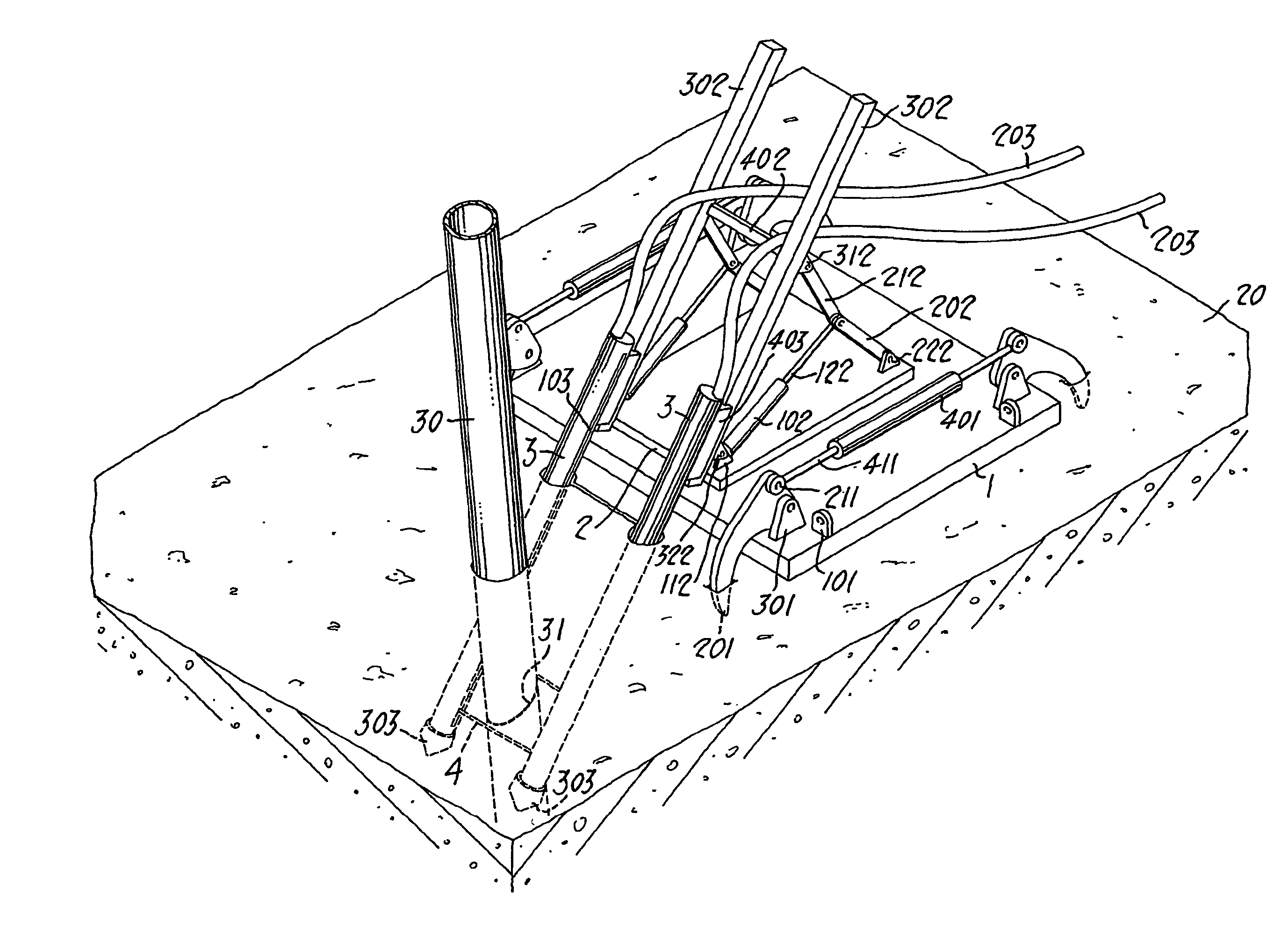
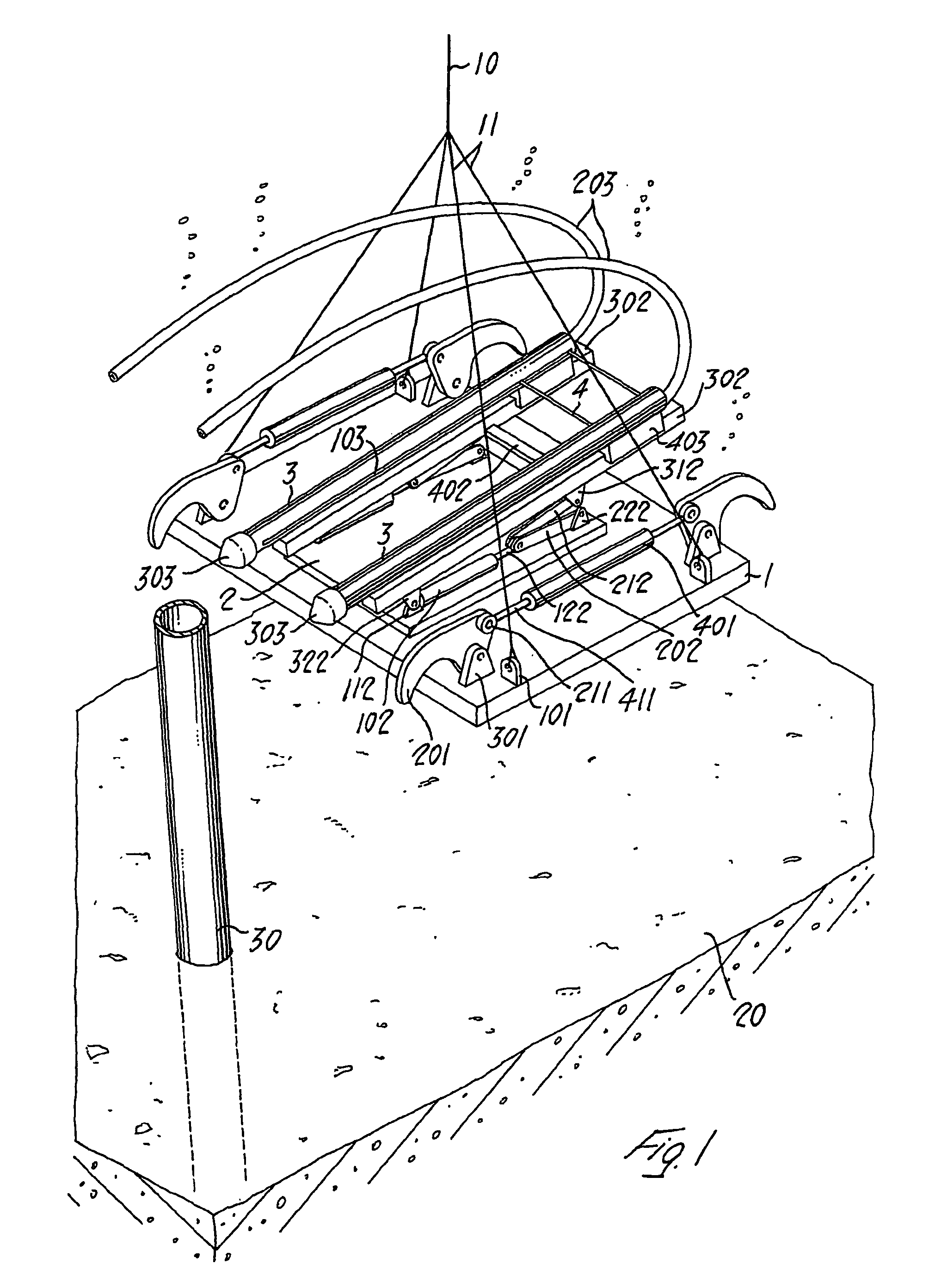
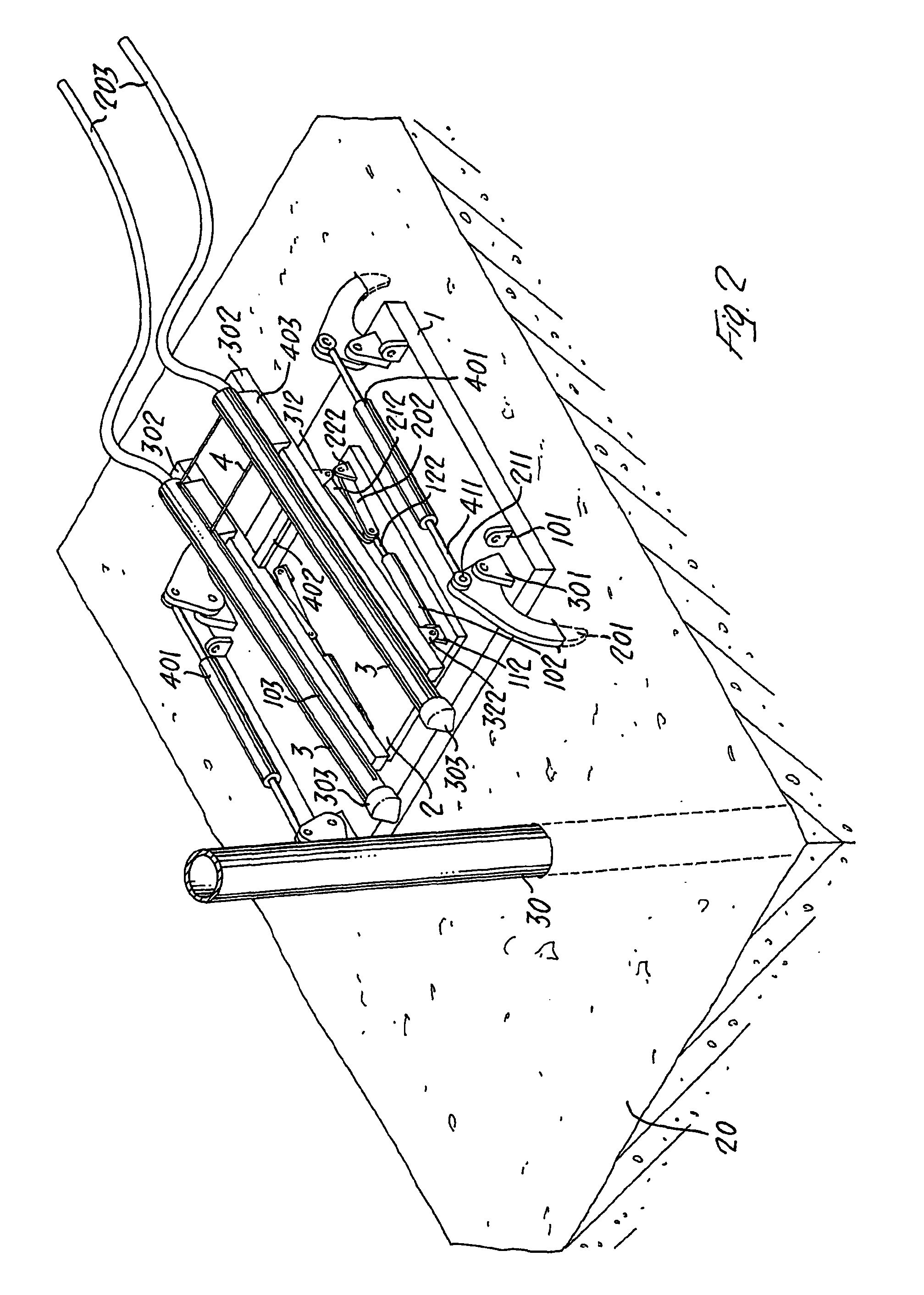
[0026]In FIG. 1 there is shown the apparatus intended to perform the method according to the present invention. Reference numeral 1 designates the supporting base of the apparatus, having a substantially rectangular shape, which is provided in proximity of each of its corners on the upper face with four lugs 101 to which there are secured the lifting rods or cables 11 which connect the base 1 to the haulage cable 10. The base 1 is further provided with means for anchoring to the bottom 20 in proximity of the structure 30 to be cut. The anchoring means comprise claws 201 which are swingable with respect to the ears 301 projecting out of the base 1 and connected to pairs of hydraulic jacks 401, provided with opposed stems 411.

[0027]To the base 1, there is connected the plate 2, to the lugs 112 of which there are hinged, at one of their ends, the two guides 302, by means of the flaps 322 projecting out of same. In proximity of the other end the guides 302 are instead connected through ...


PUM

PropertyMeasurementUnit
morphologyaaaaaaaaaa
gravityaaaaaaaaaa
shapeaaaaaaaaaa

Abstract

A method for the cutting of underwater structures below the level of the sea bottom on which they are installed, comprises determining an ideal plane of cutting, having considered the characteristic features of the structure i.e. its morphology and its positioning on the bottom, the shape and consistency of the bottom itself, and the depth below the level of the bottom at which the cut must be effected; positioning and anchoring of a cutter in proximity of the cutting area; obtainment of at least one perforation or boring in proximity of the structure through the bottom at least up to the predetermined level for the cutting of the structure, along a direction parallel to the cutting direction and preferably lying on the cutting plane; and introduction of the cutter inside the perforation or boring and cutting of the structure. An apparatus for carrying out the method is also provided.

Description

FIELD OF THE INVENTION[0001]The present invention relates to a method and an apparatus for cutting underwater structures.[0002]The cutting of submerged structures, with the purpose of removal and / or substitution of same, is presently effected by adopting different methods and by utilising apparatus of different nature.BACKGROUND OF THE INVENTION[0003]There are known devices for the cutting of submerged structures which operate with fixed blades, such as the one described for example in the document U.S. Pat. No. 3,056,267, or provided with several rotary blades co-ordinated in their action as in the document U.S. Pat. No. 4,180,047. Both apparatus however present the disadvantage of operating only on the emerging and free end of the submerged structure.[0004]In the document EP-B-0 540 834, owned by the same applicant, there is described a method and a device for cutting underwater structures which make use of a diamond cable as cutting means; the device permits the cutting of the un...

Claims


Application Information

Patent Timeline
Patent Type & Authority Patents(United States)
IPC IPC(8): E21B29/12F16L55/18B23D57/00E02D9/04
CPCB23D57/0038E02D9/04B23D57/0084E02B2017/0052Y10T83/04Y10T83/391Y10T83/647
Inventor MATTEUCCI, FRANCESCO
Owner TS TECNOSPAMEC
Why Eureka
Try Eureka