Shutter fastener system and method of installation

Active Publication Date: 2010-02-25
NORSE
View PDF5 Cites 4 Cited by
  • Summary
  • Abstract
  • Description
  • Claims
  • Application Information

AI Technical Summary

Benefits of technology

[0008]The fastener mechanisms are preferably of the type disclosed in the aforementioned patents but may vary widely in design and construction. In all cases, however, the fasteners exert a perpendicular force urging the shutter into firm engagement with the trim. Even a slight degree of looseness between a shutter and its adjacent trim may of course result in the shutter being vibrated, torn loose, and blown away by the excessively high winds encountered in a hurricane.
[0009]As disclosed in the aforementioned patents and in the present invention the latching device includes a generally S shaped spring-like latching element which in its unlatched condition resides wholly on one side of a shutter edge but which in its latched condition projects outwardly and spans the shutter edge to engage its corresponding anchor device with a strong but resilient locking force parallel to the face of the shutter. An eccentric actuator for the latching element causes a hook at the free end of the S shaped member to first swing down into engagement with the anchor device and then to pull on the device with a resilient retractive force as high as 500 pounds. Conversion of a part of this force to a resultant perpendicular force is accomplished by mean

Problems solved by technology

Even a slight degree of looseness between a shutter and its adjacent trim may of course result in the shu

Method used


Image

  • Shutter fastener system and method of installation
  • Shutter fastener system and method of installation
  • Shutter fastener system and method of installation

Examples


Embodiment Construction

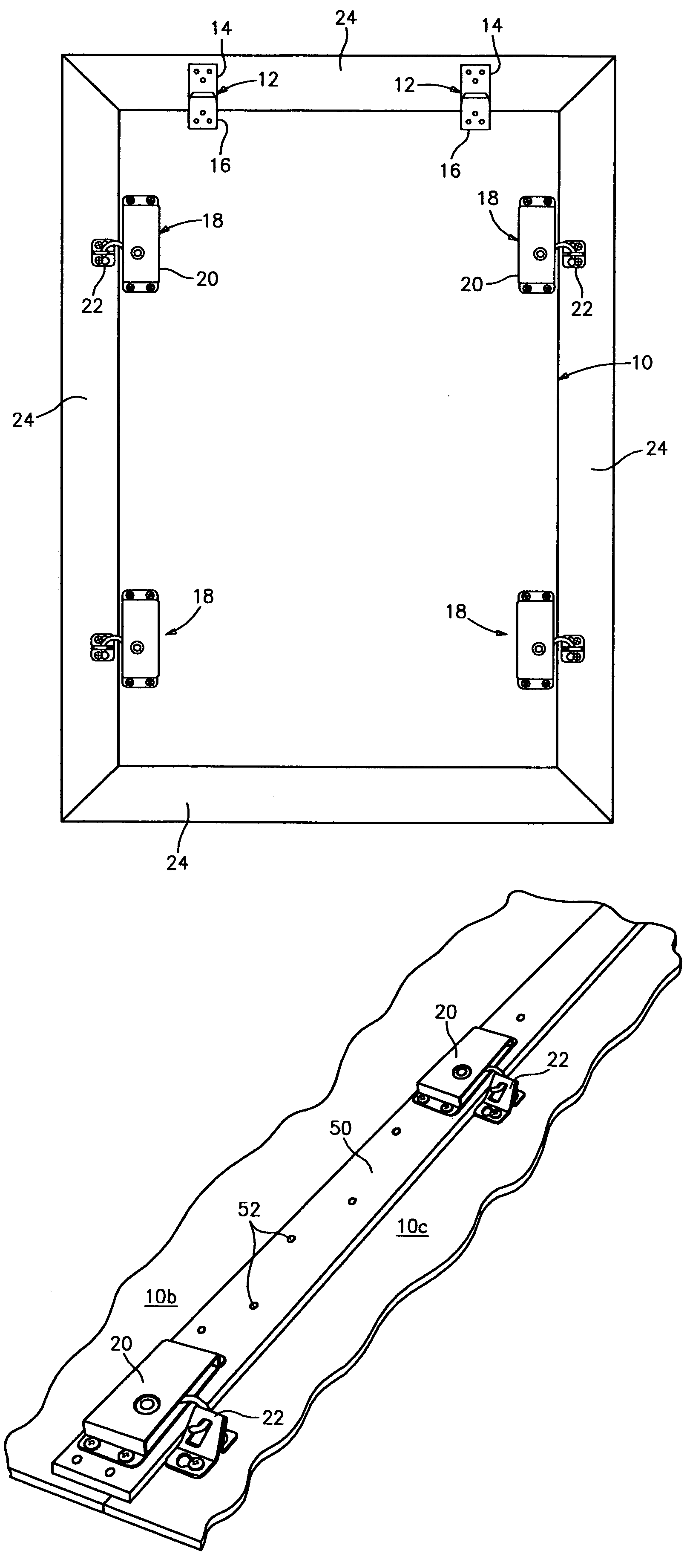
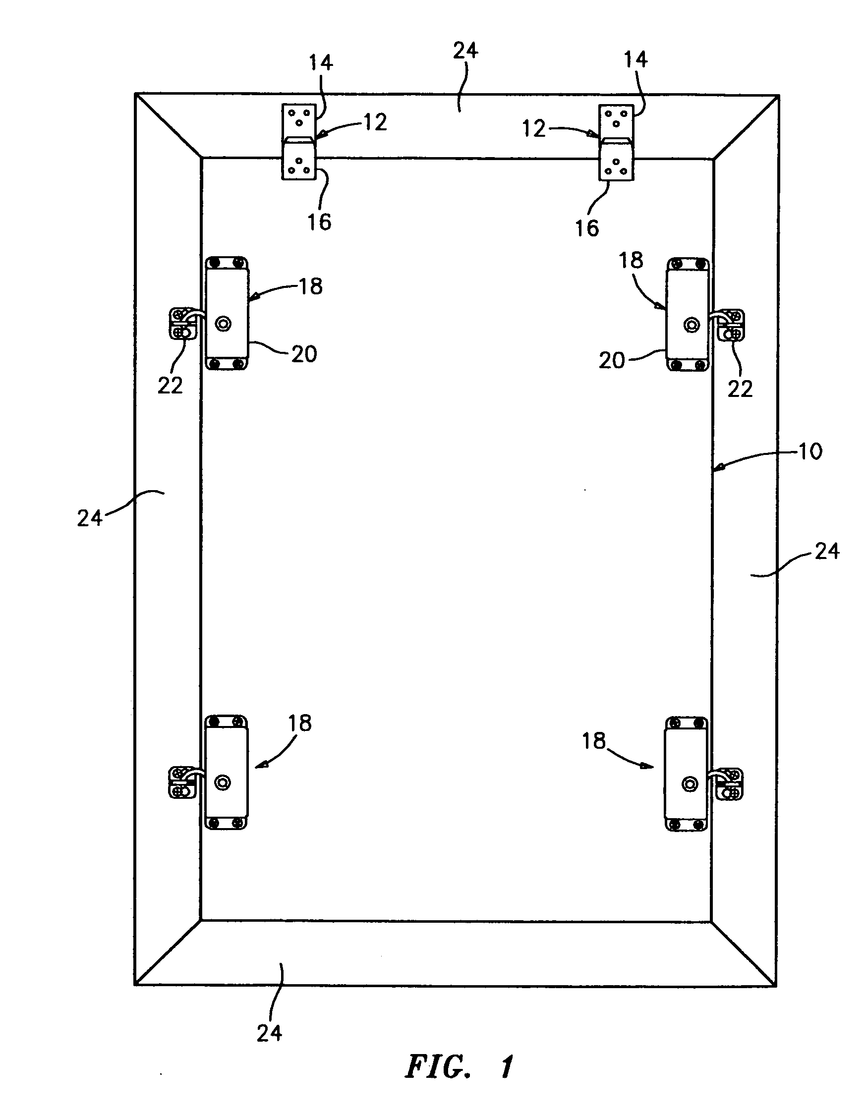
[0021]Referring particularly to FIG. 1, a hurricane shutter is indicated generally at 10 and may comprise a conventional 4×8 ft. sheet of plywood of appropriate thickness. The shutter is shown supported on co-operative vertical support means 12, 12 which may comprise simple hanger devices with an upper part 14 attached to window trim or the like and a lower part 16, attached to an upper portion of the shutter.

[0022]As will be obvious, the shutter 10, can be hung in position from outside the structure on hangers 12, 12 over a window requiring protection from hurricane winds. As will also be obvious, the shutter can be hung from inside the structure with the window open, the shutter being passed outwardly through the window in a diagonal attitude and thereafter held in position by the hangers 12, 12.

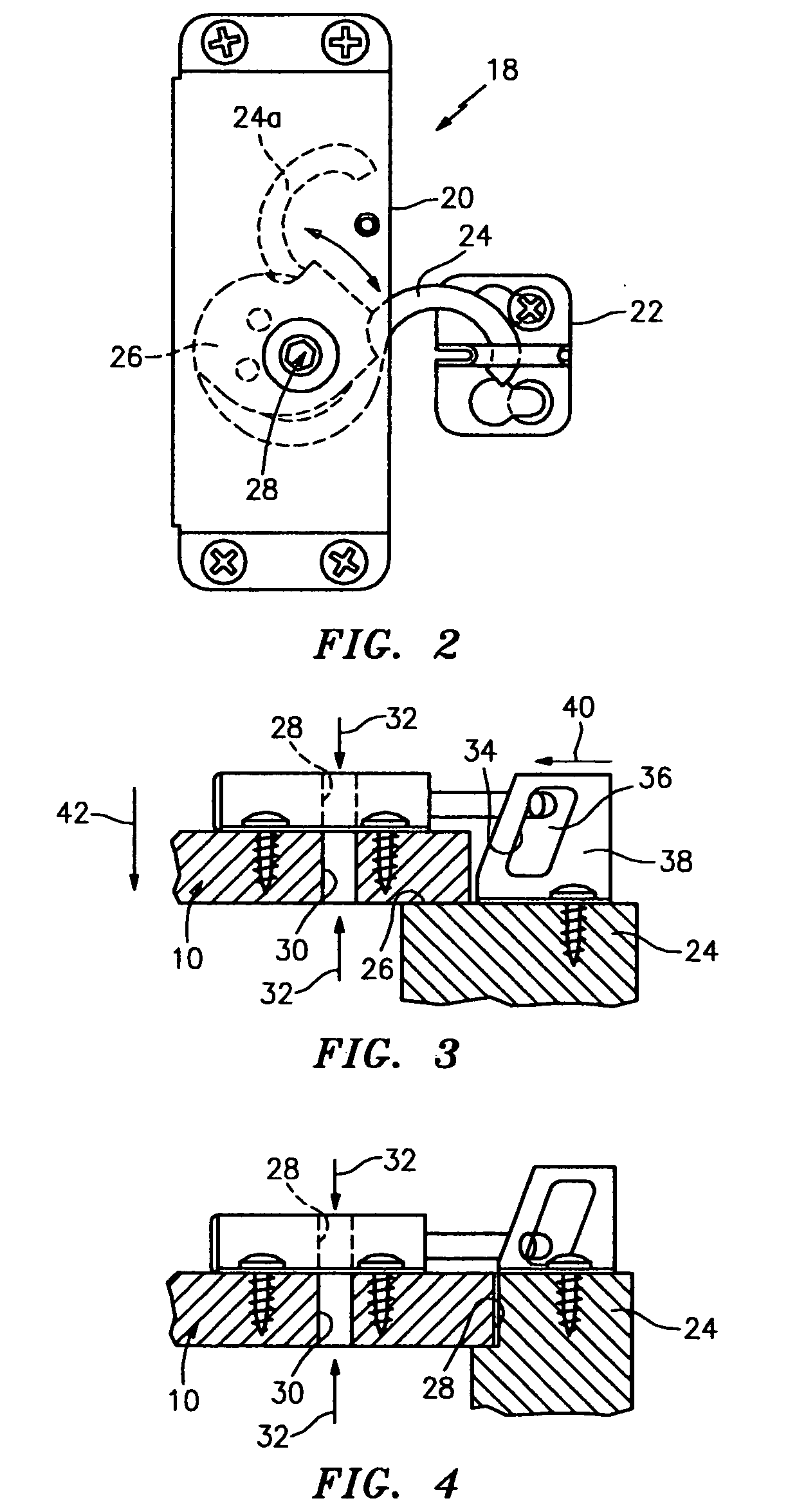
[0023]In accordance with the invention, at least one fastener mechanism is provided for securing the shutter in place. As shown, four (4) fastener mechanisms 18, 18 are shown in a rectangu...


PUM


Abstract

A shutter and fastener system comprising a shutter and two or more fastener mechanisms each comprising cooperating latching and anchor devices, one device mounted on an edge portion of the shutter and the other on an adjacent trim portion. The latching device engages the anchor device and exerts a strong pulling force substantially parallel with the surface of the shutter. The anchor device converts a portion of this force to a perpendicular force resulting in firm engagement between the shutter and the trim portion. An installation method comprises the steps of proving a shutter with a t least one latching device mounted thereon and a small opening in the shutter aligned with operating means for the device. An anchor device is provided on an adjacent trim portion and the operating means is actuated from inside the shutter though the small opening to secure the shutter in place. A hanger means for the shutter may also be provided and the need for a ladder in an elevated installation is obviated by passing the shutter outwardly through an opening and thereafter actuating one or more latching devices from within the structure.

Description

[0001]Hurricane shutters comprising sheets of plywood or more complex metallic or plastic members have in the past been fastened in place by various means ranging from simple nails and screws to complex multi-part fasteners. While generally satisfactory none of the various fastening means has been found completely satisfactory.[0002]Accordingly, it is the general object of the present invention to provide an improved shutter and fastener system which can be installed in position over a window or the like with a minimum expenditure of time and effort and which is of desirably simple construction and yet provides a superior result in securing shutters firmly in position against adjacent trim.[0003]A further object of the invention resides in the provision of a fastener system and a method of shutter and fastener installation which can be carried out without the use of a ladder for elevated windows etc.[0004]A still further object resides in the provision of a one man installation meth...

Claims


Application Information

Patent Timeline
IPC IPC(8): E06B3/30
CPCE06B2009/005E06B9/02Y10T292/0953Y10T292/1041
Inventor LANCER, ALFRED C.
Owner NORSE
Why Eureka
Try Eureka