Device for determining position

a technology for determining positions and devices, applied in medical science, dental surgery, surgery, etc., to achieve the effect of high degree of accuracy, precise surface position, and simple construction

Inactive Publication Date: 2009-05-14
NOBEL BIOCARE SERVICES AG
View PDF18 Cites 69 Cited by
  • Summary
  • Abstract
  • Description
  • Claims
  • Application Information

AI Technical Summary

Benefits of technology

[0012]By means of what is proposed above, a position-determining device is obtained which secures the assembly template in place without risks of the assembly template tilting or changing position on account of the tightening in the actual fixture dummy or fixture. In the position thus assumed with the device, the assembly template can thus be assigned supporting or cooperating parts via which the assembly template cooperates with the jaw-bone model in order to obtain, with a high degree of accuracy, a precise position of the surface in question. The device also has a comparatively technically simple construction and can, for example, work with an external cone on an expansion screw and an internal cone on the expansion surface so that the parallelism between the cooperating surfaces on the expansion spacer and the sleeve in the dental bridge is present and is maintained during the subsequent work on the dental bridge.

Problems solved by technology

The positional determination or fixing of the assembly template in question, with associated sleeves, to or on the jaw bone model must also be such that, when the template or template parts are screwed into or onto the jaw-bone model, it is not possible for the template or template parts, during the screwing or tightening, to permit changes in the position of the sleeves, which must not be allowed to tilt or otherwise change their positions in relation to the fixture dummy or fixture dummies during the tightening.

Method used


Image

  • Device for determining position
  • Device for determining position
  • Device for determining position

Examples


Embodiment Construction

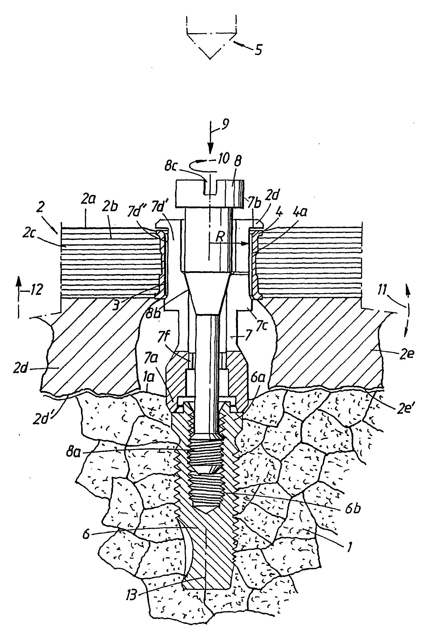
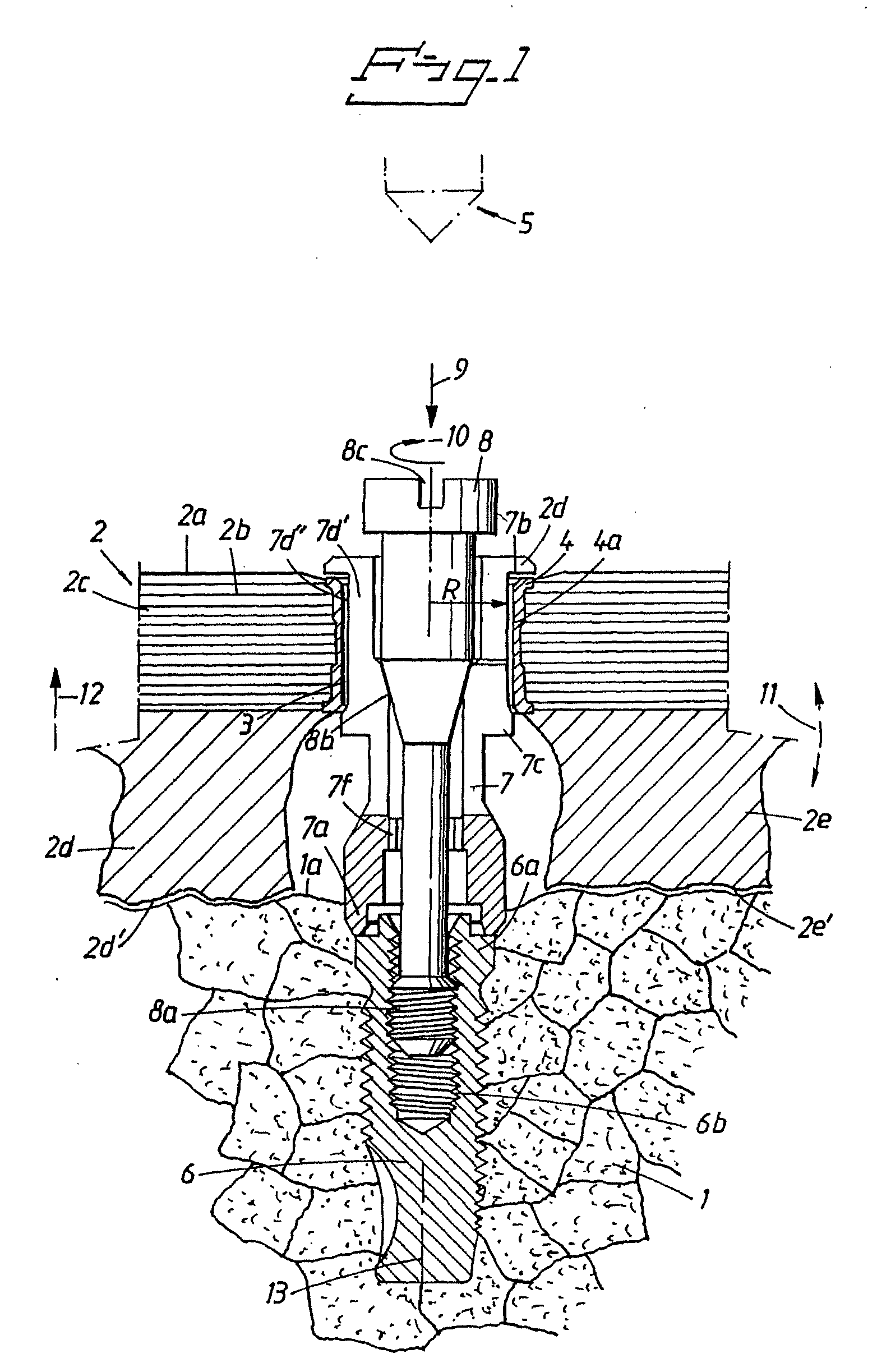
[0020]FIG. 1 shows a jaw-bone model labeled 1. The jawbone model represents a jaw bone of a patient. The model can be produced on different principles and thus, in one embodiment, the jaw model can be produced using stereolithography equipment known per se. An assembly template 2 is applied to the top surface 1a of the model. The assembly template is provided with a number of through-holes, of which one hole 3 is shown in the figure. The hole is obtained with the aid of a sleeve 4 which will constitute a guide member for a hole-forming member 5 shown diagrammatically or symbolically in connection with the template. The sleeve can be made of metal (titanium) or alloy. The template is secured in fixture dummies, of which one fixture dummy has been shown by 6 in FIG. 1. The fixture dummy can be of a type known per se and available on the open market, for example from Nobel Biocare AB. The assembly template can consist of a shell 2a which includes carbon fibre reinforcements 2b in a man...


PUM


Abstract

An arrangement for determining position and fixation of an element in a vertical direction and a transverse direction in relation to a part in or on a bone or a model of a bone. A sleeve includes an inner surface. An expansion spacer extends through the sleeve and includes an outer sleeve engaging surface and an inner conical expansion surface. The expansion spacer includes a first flange configured to engage a first end of the sleeve and a second flange configured to engage a second end of the sleeve when the expansion spacer is expanded to vertically fix the expansion spacer with respect to the sleeve. An expansion screw extends through the expansion spacer and includes an outer conical expansion surface configured to cooperate with the inner conical expansion surface on the expansion spacer to radially expand the expansion spacer causing the outer sleeve engaging surface on the expansion spacer to engage the inner surface of the sleeve, thereby determining the position of the sleeve relative to the part and fixing the sleeve causing the expansion spacer to engage the sleeve. Radial expansion of the expansion spacer causes an outer surface of the expansion spacer to be positioned substantially parallel to the inner surface of the sleeve. An assembly template is configured to be arranged on soft tissue overlying the bone and includes a through hole extending therethrough, wherein the sleeve is arranged in the through hole.

Description

CROSS-REFERENCE TO RELATED APPLICATIONS[0001]This application is a continuation of copending U.S. patent application Ser. No. 10 / 451,530 filed Jun. 24, 2003, which claims priority to Swedish patent application 0004886-8 filed 29 Dec. 2001 and is the national phase under 35 U.S.C. § 371 of PCT / SE01 / 02900.FIELD OF THE INVENTION[0002]The present invention relates to a device for determining the position of an element, for example a sleeve, on the one hand in the vertical direction in relation to an anchoring part or structural part, for example a fixture or fixture dummy, in or on a bone, for example a jaw bone, or a model of a bone, and on the other hand in the transverse direction in relation to the longitudinal axis of the part.[0003]The invention is intended, inter alia, to be used in connection with the production and the use of assembly templates which are used for hole-forming elements (drill / drills, attachments, etc.) in the jaw bone. The assembly template can be used in connec...

Claims


Application Information

Patent Timeline
Patent Type & Authority Applications(United States)
IPC IPC(8): A61C3/00A61C8/00A61B17/16
CPCA61C8/0001B33Y80/00
Inventor BRAJNOVIC, IZIDOR
Owner NOBEL BIOCARE SERVICES AG
Why Eureka
Try Eureka