Rack-mount power supply device and battery pack including detachable connector

a power supply device and battery pack technology, applied in the direction of secondary cell servicing/maintenance, cell component details, cell components, etc., can solve the problems of reduced safety, reduced operation efficiency, and dangerous wiring, so as to improve safety upon placement and detection accuracy

Inactive Publication Date: 2014-01-16
SANYO ELECTRIC CO LTD
View PDF2 Cites 67 Cited by
  • Summary
  • Abstract
  • Description
  • Claims
  • Application Information

AI Technical Summary

Benefits of technology

[0038]In the above-described battery pack, the detachable connectors are provided with the main placement/removal detection terminals and the main connection terminals which are connected to each other after the output terminals and the input terminals are connected to each other at timing at which the battery pack is placed in the rack main body, and the sub-placement/removal detection terminals and the sub-connection terminals which are connected to each other before the output termi...

Problems solved by technology

Note, however, that since the larger the number of battery packs connected in series with each other, the higher the output voltage, there is a problem that their wiring becomes dangerous.
Thus, it is extremely dangerous if an operator receives an electric shock during an operation.
Thus, it is likely that the operation is performed in a dark narrow space which is the back surface side of the rack, causing not only a reduction in the efficiency of the operation, but also a reduction in safety.
Hence, in the battery pack, when the ...

Method used


Image

  • Rack-mount power supply device and battery pack including detachable connector
  • Rack-mount power supply device and battery pack including detachable connector
  • Rack-mount power supply device and battery pack including detachable connector

Examples


Embodiment Construction

)

[0051]Embodiments of the present invention will be described below based on the drawings. Note, however, that the embodiments shown below exemplify rack-mount power supply devices and battery packs including detachable connectors for embodying the technical idea of the present invention, and the present invention does not specify rack-mount power supply devices and battery packs including detachable connectors to those shown below. In the present specification, the members shown in the claims are not specified to the members in the embodiments.

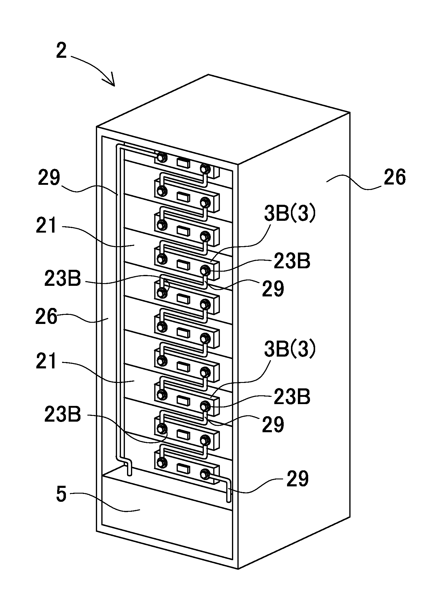
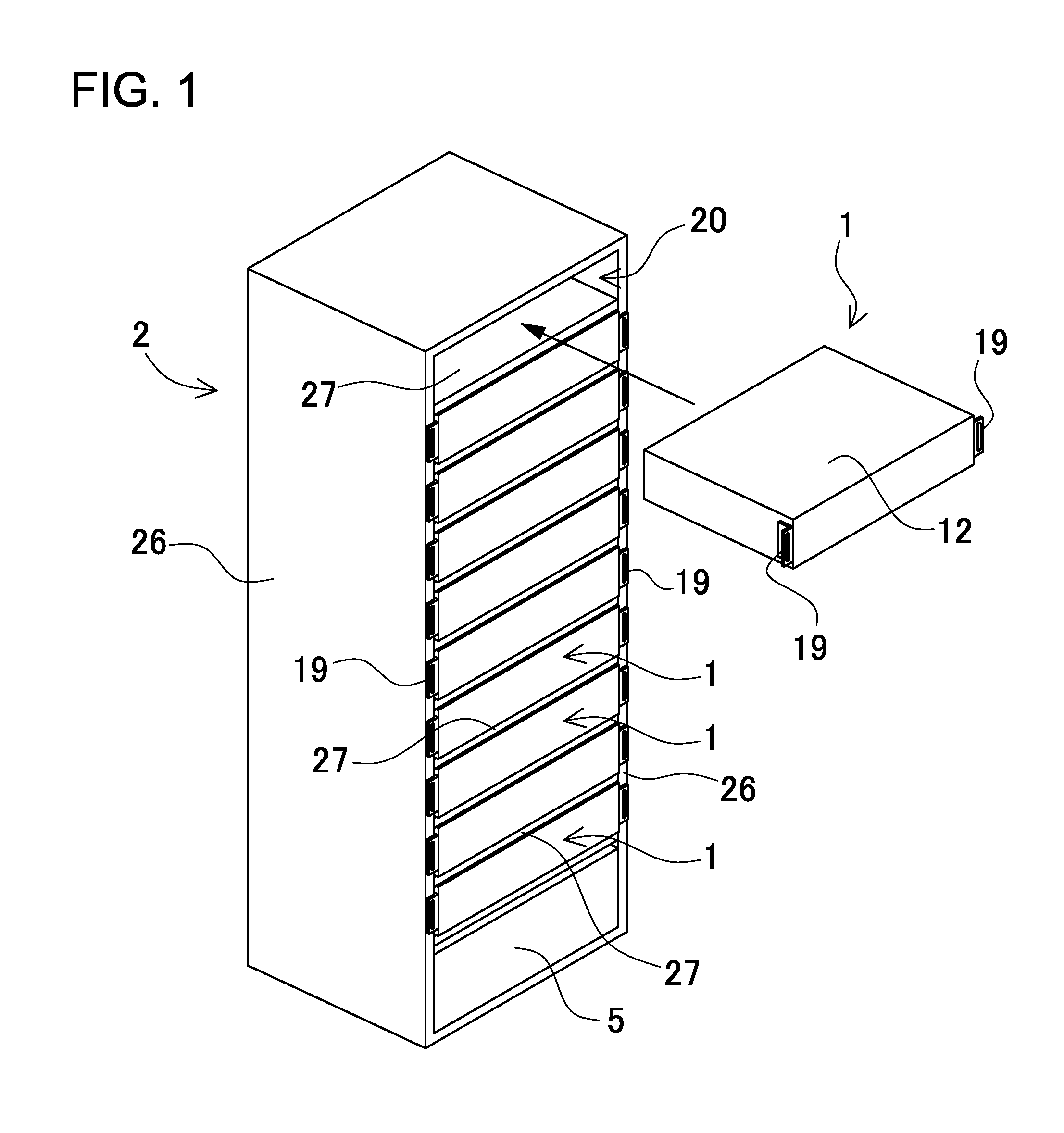
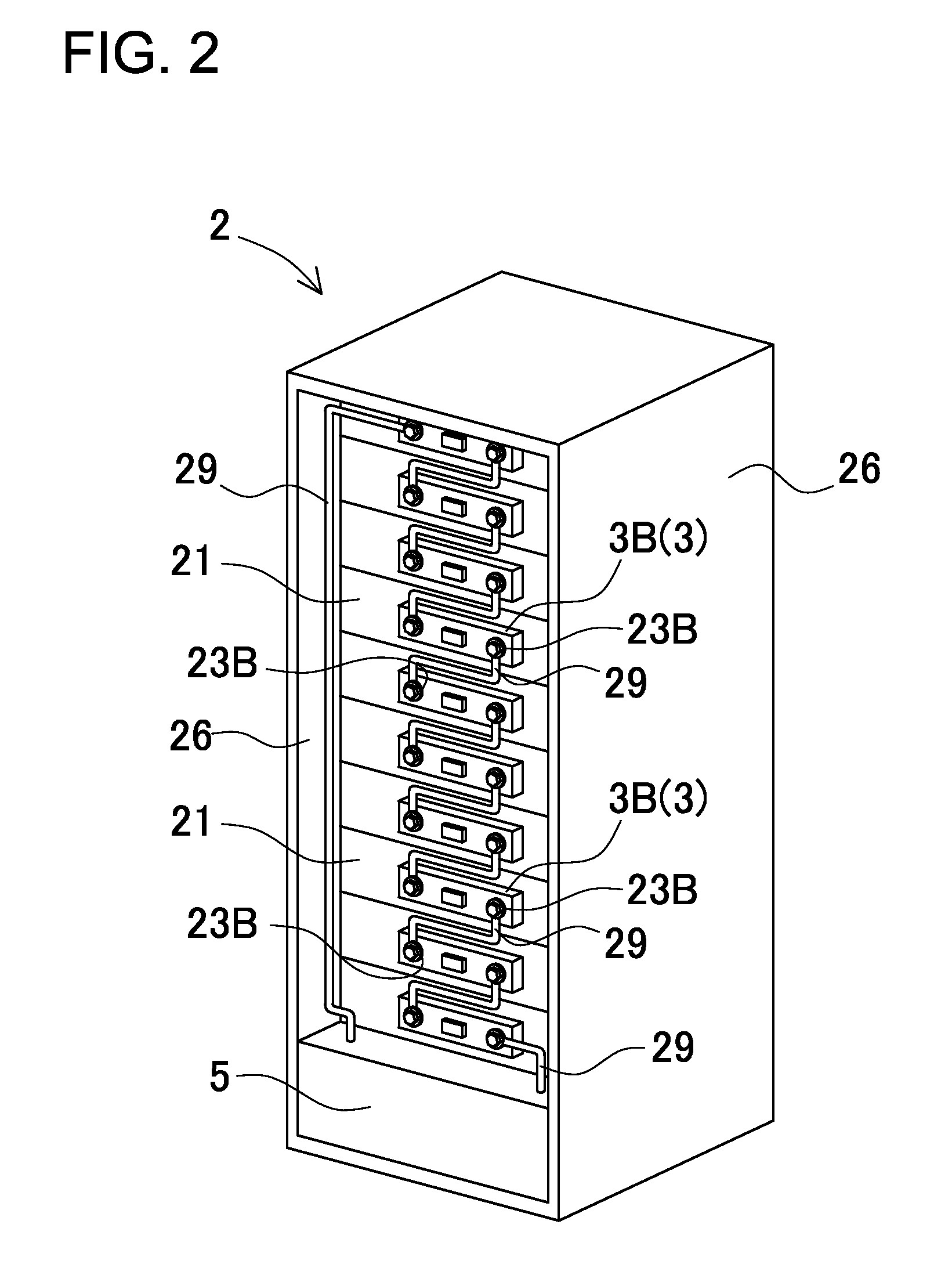
[0052]A rack-mount power supply device of the present invention can be used as placement-type electricity storage equipment. For example, the rack-mount power supply device can be used as a power supply for home use or for factories in a power supply system that performs charging with sunlight, midnight power, etc., and performs discharging when necessary, or can also be used as a power supply for street lights that performs charging with day...


PUM


Abstract

In a rack-mount power supply device, a plurality of battery packs are removably placed in a rack main body. In each battery pack, a battery including a plurality of unit cells is housed in an outer case, and positive and negative output terminals are provided so as to come out on a back surface of the outer case. The rack main body includes a plurality of housing spaces housing the battery packs, respectively, and includes input terminals on a facing surface which is an inner surface of each housing space and which faces output terminals, the output terminals being to be electrically connected to the input terminals in a fitting state. In the rack main body, the input terminals are wired in a predetermined connection state on the back sides of the respective facing surfaces. In the rack-mount power supply device, the plurality of battery packs are connected to each other in a predetermined connection state, with the plurality of battery packs guided into the housing spaces of the rack main body and the output terminals connected to the input terminals.

Description

BACKGROUND OF THE INVENTION[0001]1. Field of the Invention[0002]The present invention relates to a rack-mount power supply device that houses in a rack a plurality of battery packs, each including a plurality of rechargeable unit cells, and to a battery pack including detachable connectors which is removably placed in a rack.[0003]2. Description of the Related Art[0004]A power supply device that charges a battery with midnight power of a utility power supply or by solar power generation, and uses the battery power as a power supply is used at home and in factories, etc., enabling to achieve a reduction in electricity costs. In addition, the power supply device can be used conveniently as a backup power supply for various types of electrical equipment. This type of power supply device includes multiple rechargeable unit cells to increase capacity. Multiple unit cells can increase output voltage by being connected in series with each other, and can increase output current by being con...

Claims


Application Information

Patent Timeline
IPC IPC(8): H01M10/42H01M2/10H01M50/204H01M50/296H01M50/503
CPCH01M10/425H01M2/1077H01M10/4207H01M10/482H01M10/4257Y02E60/10H01M50/204H01M50/296H01M50/503
Inventor UEHARA, YUJIYAMAGUCHI, MASAOHARADA, TAKANORI
Owner SANYO ELECTRIC CO LTD
Why Eureka
Try Eureka