Full port externally gimballed joint

a gimbal and full-port technology, applied in the direction of threaded fasteners, screws, rod connections, etc., can solve the problems of ducting limited freedom of movement, and ducting and joints being stressed

Inactive Publication Date: 2006-05-09
UNISON INDUSTRIES
View PDF9 Cites 17 Cited by
  • Summary
  • Abstract
  • Description
  • Claims
  • Application Information

AI Technical Summary

Problems solved by technology

Such joints also allow the ducting limited freedom of movement when the ducting is subject to operational stresses when the engine is operating, particularly in aircraft.
High temperatures and fluctuations in pressure can cause stress on the ducting and joints.
Gimbal joints to accommodate high temperature high pressure flows have been developed but they have narrow areas in the middle of the joints which restricts flow and causes flow losses in the ducts.
Some of the bending has been so pronounced, that not only did the bending limit the amount of rotation the joint could accommodate, but pins also fell out.

Method used


Image

  • Full port externally gimballed joint
  • Full port externally gimballed joint
  • Full port externally gimballed joint

Examples


Embodiment Construction

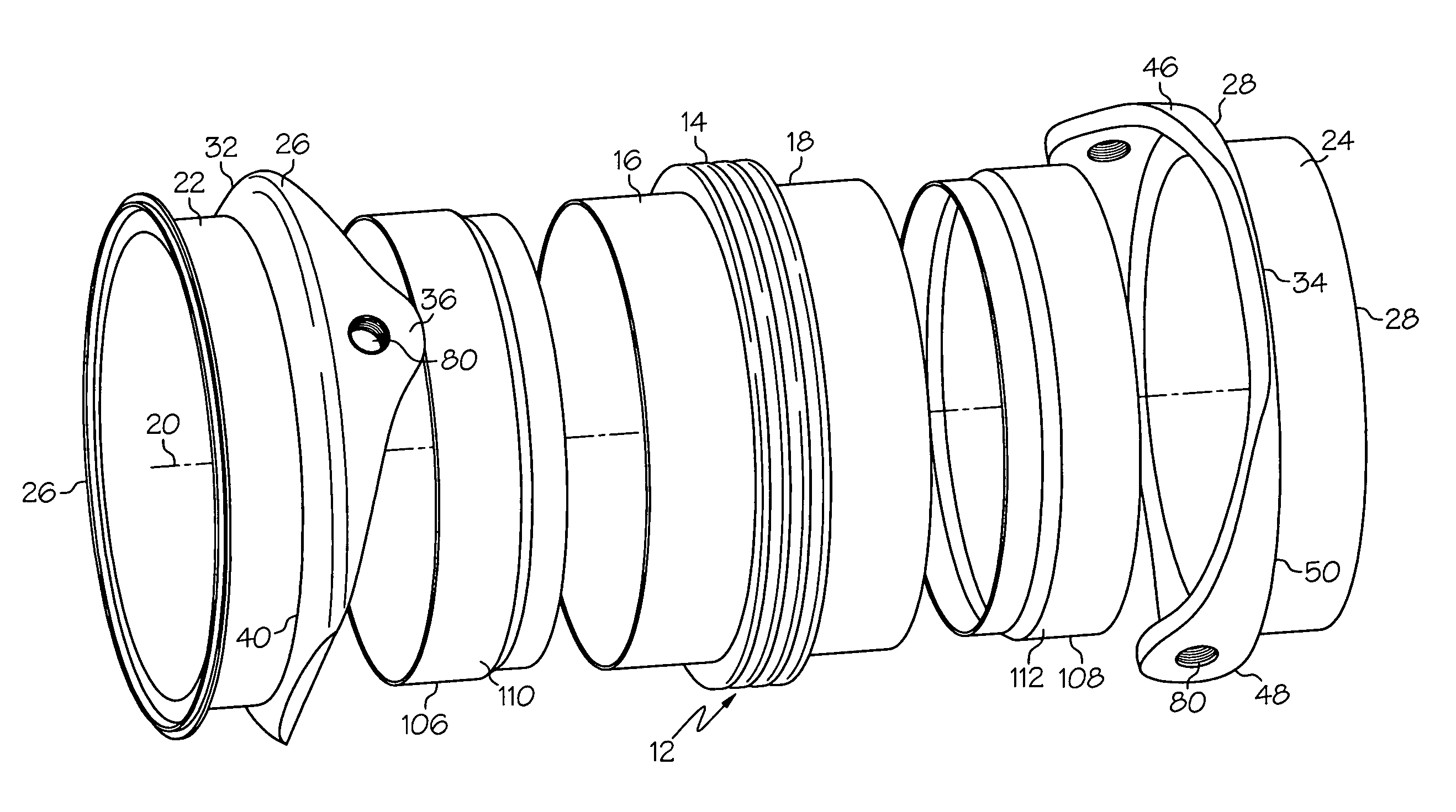
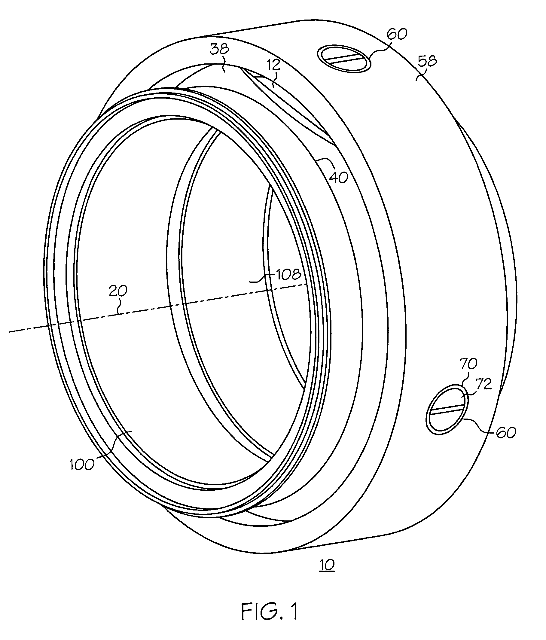
[0019]Illustrated in FIGS. 1 and 3 is gimballed joint 10 including an annular bellows seal 12 having a middle section bellows 14 between forward and aft cylindrical seal sections 16 and 18 circumscribed about a joint centerline 20. The forward and aft cylindrical seal sections 16 and 18 are mounted within and to forward and aft shroud annular sections 22 and 24, respectively, of forward and aft shrouds 26 and 28. The forward and aft shrouds 26 and 28 have forward and aft clevises 32 and 34, respectively. The forward and aft clevises 32 and 34 are spaced 90 degrees apart from each other. The forward clevis 32 has first and second forward lugs 36 and 38 spaced 180 degrees apart around a forward periphery 40 of the forward shroud annular section 22. The aft clevis 34 has first and second aft lugs 46 and 48 spaced 180 degrees apart around an aft periphery 50 of the aft shroud annular section 24.

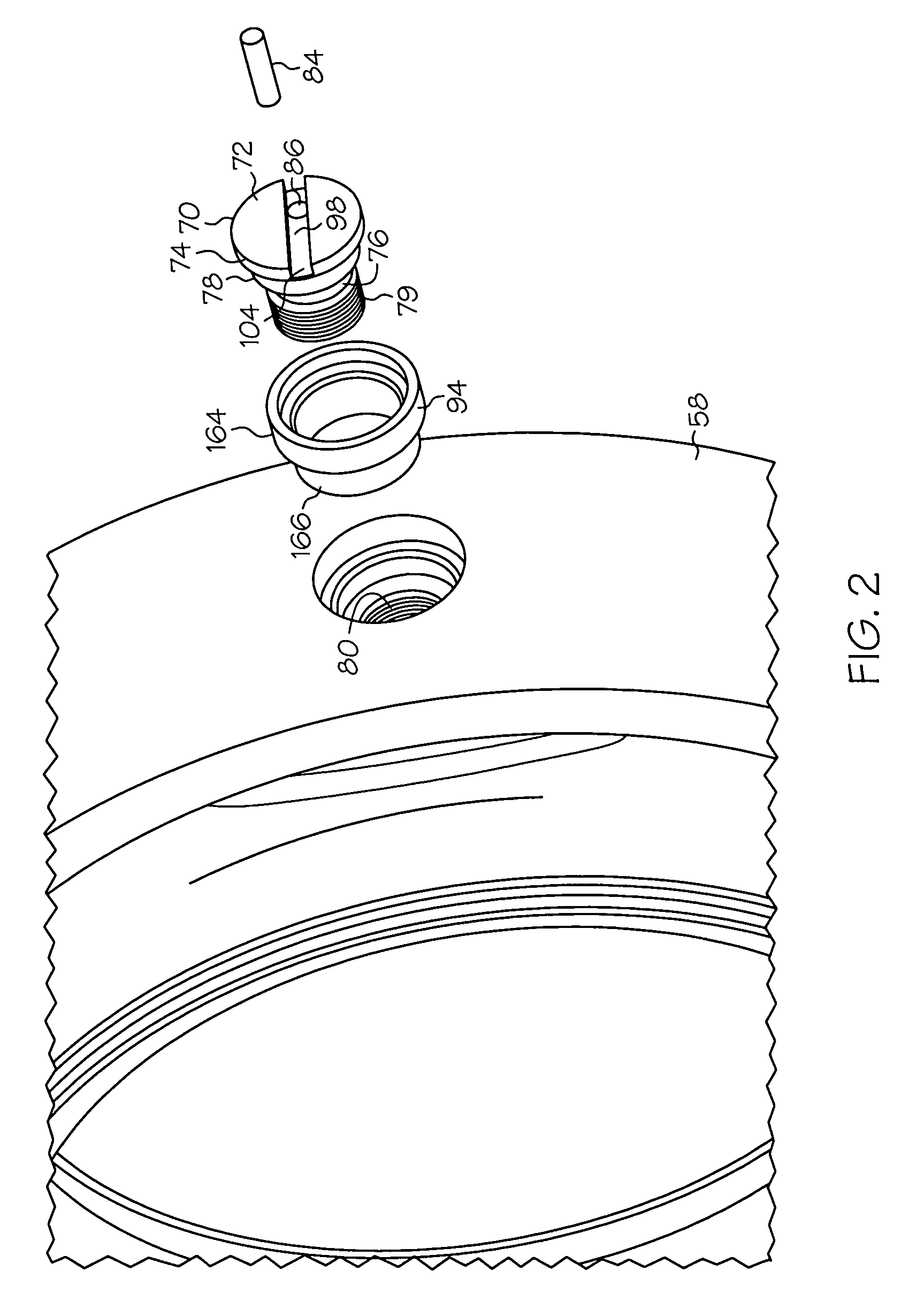
[0020]Additionally referring to FIG. 5, internally threaded holes 80 are disposed through the...


PUM


Abstract

A gimballed joint includes an annular bellows seal circumscribed about a joint centerline mounted within forward and aft shrouds having clevises with lugs and a threaded hole disposed through each of lugs. A ring circumscribed about the lugs has counterbored holes. Each of the counterbored holes is aligned with one of the threaded holes. Pins having heads and shanks extending inwardly therefrom are disposed through and the heads engage the counterbored holes. Externally threaded portions of the shanks are threaded into internally threaded holes in the each of the lugs. A key is disposed through a key hole extending inwardly through each of the heads and through threaded together portions of external threads of each of the externally threaded portions and internal threads of each of the internally threaded holes. In one embodiment wear bushings are disposed in the counterbored holes between the heads and the ring.

Description

BACKGROUND OF THE INVENTION[0001]1. Field of the Invention[0002]This invention relates to joint assemblies for ducting and, more particularly, gimbal joints used to flexibly connect sections of ducting and, more particularly, high pressure aircraft ducting together so that the sections of ducting can swivel at the joints relative to each other.[0003]2. Description of Related Art[0004]Gas turbine engines produce very high pressure air which is ducted for use in various parts of the engine and / or other external applications such as in an aircraft. The high pressure ducting must often have flexible joints to accommodate the irregular internal passages of various aircraft and other hardware and machinery in which the ducting is used. To meet this requirement, sections of ducting are often connected by gimbal joints which provide the necessary flexibility during installation and operation of the ducting during engine operation. Such joints also allow the ducting limited freedom of moveme...

Claims


Application Information

Patent Timeline
Patent Type & Authority Patents(United States)
IPC IPC(8): F16L27/04F16B39/02F02K1/80F16B7/18F16L27/11
CPCF02K1/80F02K1/805F16L27/0857F05D2240/55Y02T50/671Y02T50/60
Inventor CHRISTIANSON, ERIC JONHILL, JOHN SAMUELDAMELE, ANTHONY FREDRIC
Owner UNISON INDUSTRIES
Why Eureka
Try Eureka