Adjustable clamp-on lamp with ball-head

a technology of clamping lamp and ball head, which is applied in the field of clamping lamps, can solve the problems of not being positioned, not being versatile, and being too large to fit on the mirror for shower use,

Inactive Publication Date: 2006-05-09
SHOWERTEK
View PDF6 Cites 91 Cited by
  • Summary
  • Abstract
  • Description
  • Claims
  • Application Information

AI Technical Summary

Problems solved by technology

Heretofore portable clamp-on lamps were large and unwieldy and could not be adjusted to shine light in a relatively wide range of areas.
E.g., existing clamp on lamps were too large to fit on mirrors for use in a shower and were not versatile, i.e., they could not be positioned so that they illuminated the mirror or the user, such as a man shaving.
Also existing clamp-on lamps were too heavy to clamp onto such a mirror, they were awkward to use, were not waterproof, and / or required mains electrical power, which was dangerous and unwieldy for a shower.

Method used


Image

  • Adjustable clamp-on lamp with ball-head
  • Adjustable clamp-on lamp with ball-head
  • Adjustable clamp-on lamp with ball-head

Examples


Embodiment Construction

—PREFERRED EMBODIMENT—FIGS. 1 TO 7

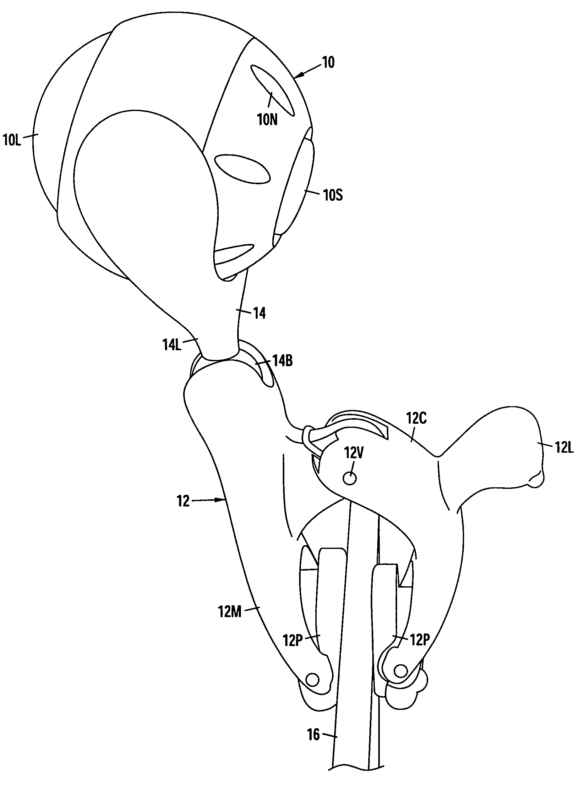
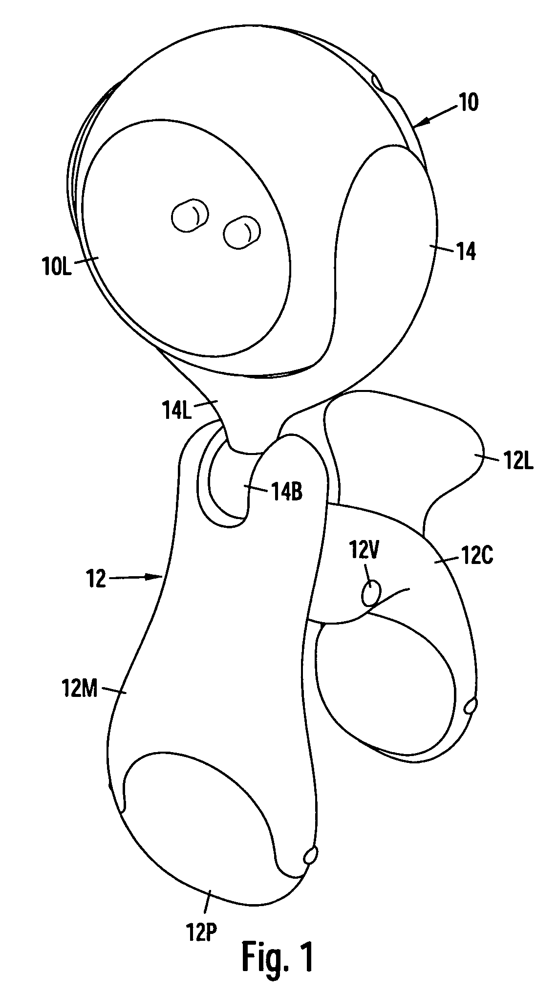
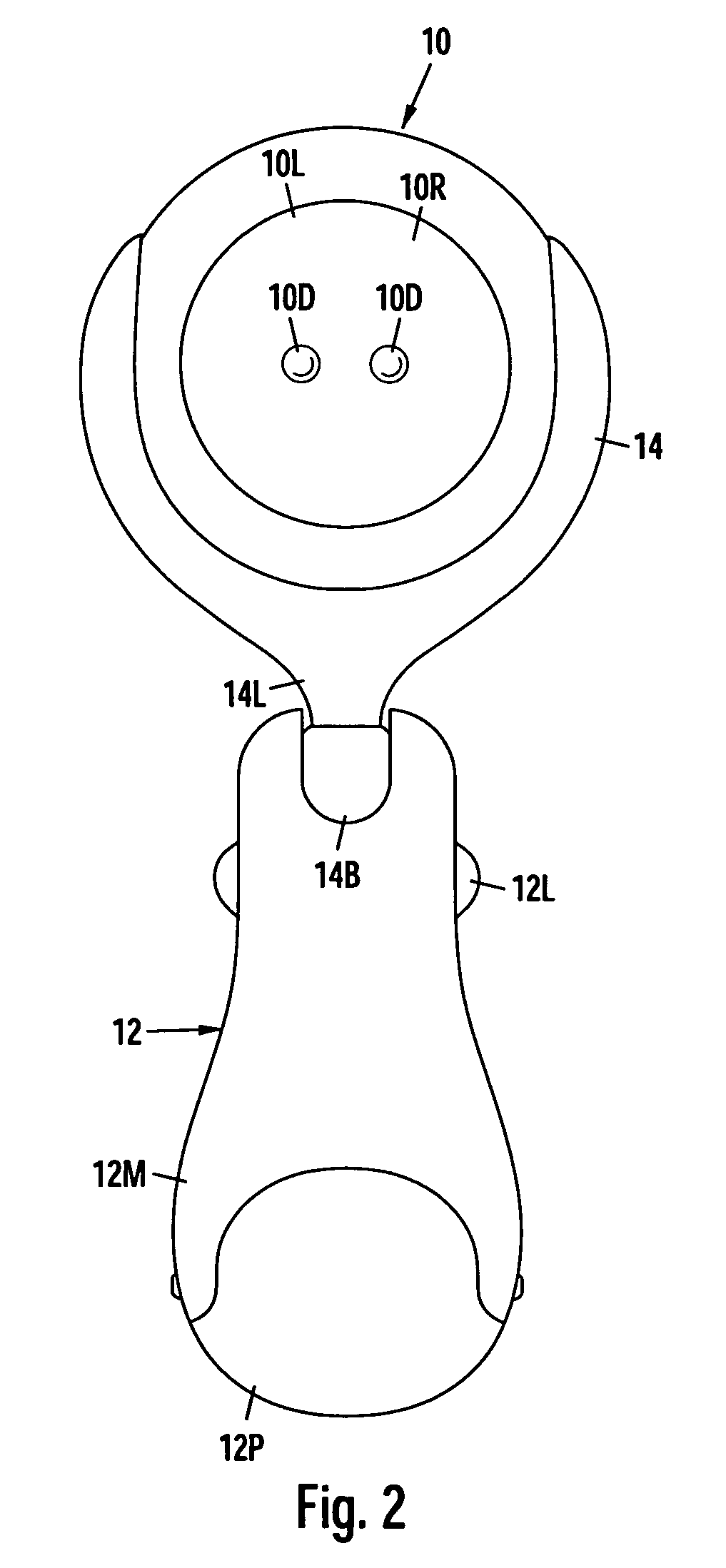
[0017]FIG. 1 is a perspective view taken from the front and above of my clip-on lamp. It has a ball or spherical head 10 at its upper end and a holding clamp 12 at its base. Ball head 10 is pivotably, springably, and frictionally mounted between the tines of a ball-holding fork 14 that forms the upper end of clamp 12. The ends of the tines have cupped or concave inner sides (FIG. 7) that conformingly mate with the concave surface of the ball head. The tines of the fork meet at a base that has a single leg 14L (FIG. 1) that extends down from the tines and has a small ball 14B at its lowermost end that permits the fork to swivel.

[0018]The bottom part of holding clamp 12 comprises a clip that has two legs, a main or generally straight leg 12M and a pivotable curved leg 12C that is pivoted on main leg 12M. The pivot of leg 12C contains a spring that urges leg 12C against leg 12M, but the legs are shown spread apart for better illustration. The end of ea...


PUM


Abstract

A clip-on task lamp has a ball-shaped head that is pivotally and frictionally mounted between the cup-shaped ends of two tines of a ball-holding fork so that the ball-head can be rotated to any position. The ball-head has a front lens with two LEDs that are backed by a reflector. The ball has a flexible two-state pushbutton switch on the rear side and an internal battery. The base of the ball-holding fork comprises a single leg with a small swivel ball. The lamp has a clamp part that has, at its top end, two arms with two respective cup ends that hold the small swivel ball by friction fit. The base end of the clamp part comprises two legs, a shorter one of which is springably pivoted on an ear of the other. The end of each leg has a swivel pad and the shorter leg has a projection for facilitating spreading the legs so that they can be sandwiched around a member and clamped to it.

Description

BACKGROUND[0001]1. Field of Invention[0002]This invention relates generally to lamps, specifically to a clamp-on lamp which can swivel and pivot to a wide range of positions.[0003]2. Prior Art[0004]Heretofore portable clamp-on lamps were large and unwieldy and could not be adjusted to shine light in a relatively wide range of areas. E.g., existing clamp on lamps were too large to fit on mirrors for use in a shower and were not versatile, i.e., they could not be positioned so that they illuminated the mirror or the user, such as a man shaving. (One such mirror is shown in my patent U.S. Pat. No. 5,953,157 (1999).) Also existing clamp-on lamps were too heavy to clamp onto such a mirror, they were awkward to use, were not waterproof, and / or required mains electrical power, which was dangerous and unwieldy for a shower.OBJECTS AND ADVANTAGES[0005]Accordingly, several advantages of some aspects of the invention are to provide an improved clamp-on lamp that can be adjusted to shine light ...

Claims


Application Information

Patent Timeline
Patent Type & Authority Patents(United States)
IPC IPC(8): F21V21/088F21V21/30
CPCF21V21/0885F21L4/04F21V31/00F21Y2101/02F21Y2115/10
Inventor CHRISTIANSON, THOMAS R.
Owner SHOWERTEK
Why Eureka
Try Eureka