Push button switch assembly

Active Publication Date: 2007-05-10
ILLINOIS TOOL WORKS INC
View PDF11 Cites 46 Cited by
  • Summary
  • Abstract
  • Description
  • Claims
  • Application Information

AI Technical Summary

Benefits of technology

[0007] Certain embodiments of the present invention provide a switch assembly configured to be secured to a panel. The switch assembly includes an integrally formed p

Problems solved by technology

Further, after the switch is assembled and in use, the printed circui

Method used


Image

  • Push button switch assembly
  • Push button switch assembly
  • Push button switch assembly

Examples


Embodiment Construction

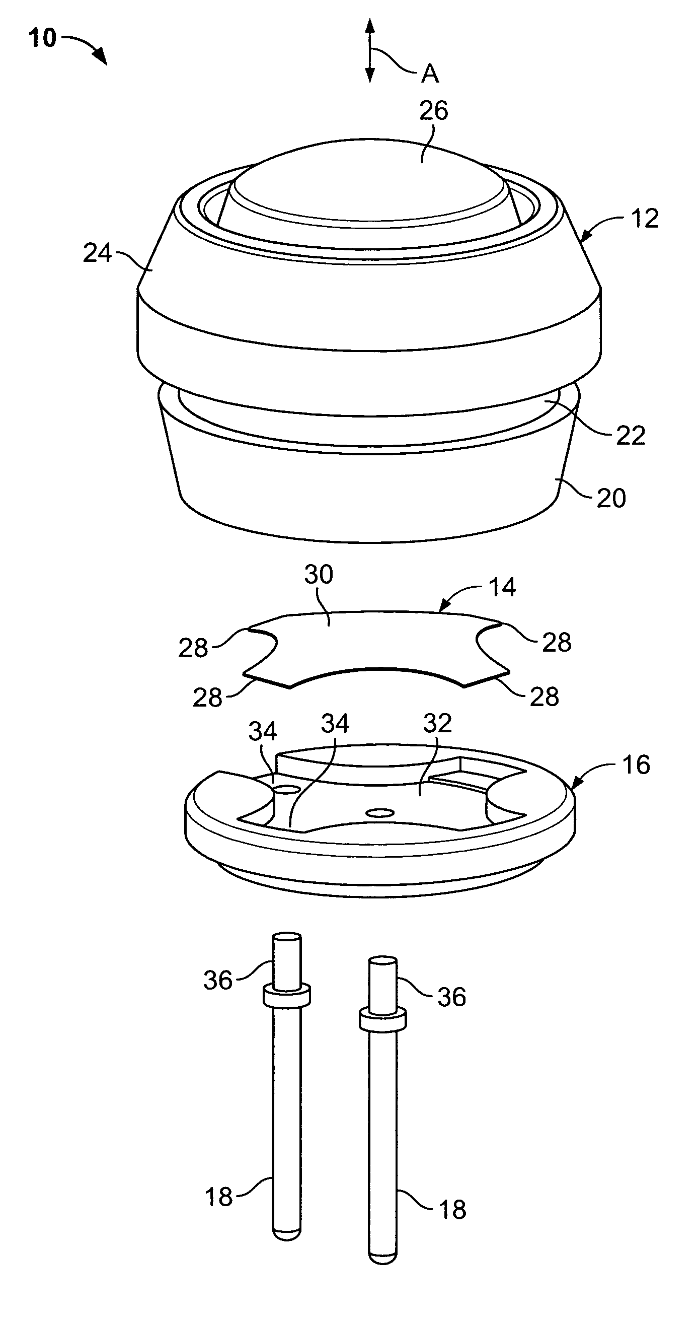
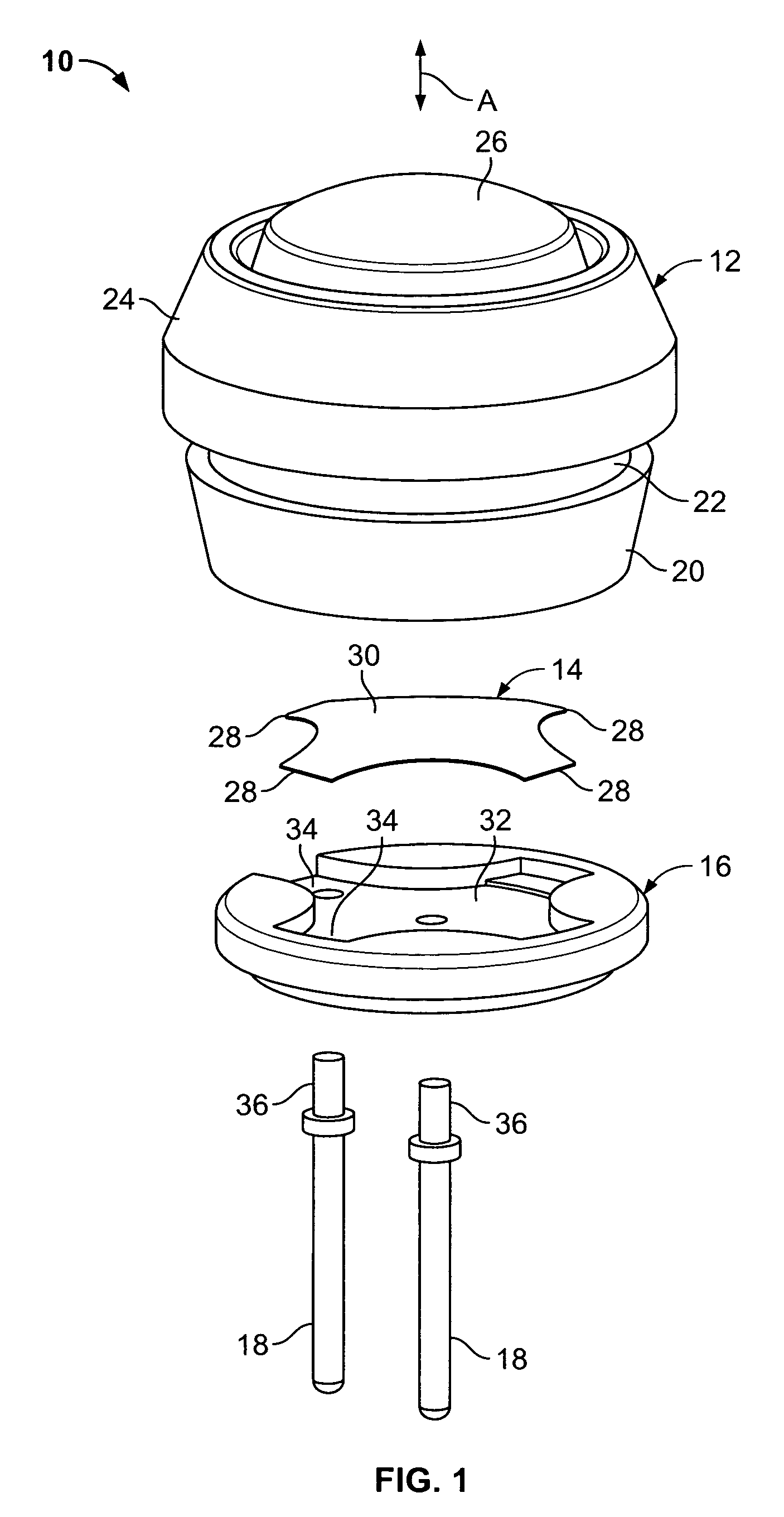
[0015]FIG. 1 illustrates an isometric exploded view of a push button switch assembly 10 according to an embodiment of the present invention. The push button switch assembly 10 includes a push button housing 12, a snap dome 14, a retaining disk 16, and two terminals 18.

[0016] The push button housing 12 is single unit that may be formed of an elastomeric material. That is, all the components of the push button housing 12 are integrally formed or molded as a single piece. The elastomeric push button housing 12 provides a sealed environment that protects the internal components from moisture infiltration.

[0017] The push button housing 12 includes a base 20 having an annular notch 22 formed proximate a circumferential sheath 24. The sheath 24 surrounds a circumference of a semi-spherical button 26. The button 26 is configured to move relative to the sheath 24 through the directions noted by arrow A. The notch 22 is configured to be received and retained by a panel or other such structu...


PUM


Abstract

A switch assembly includes a unitary push button housing including an actuable button, a retainer having a first surface and a second surface, in which the retainer is secured within the push button housing, a snap dome secured on the first surface of the retainer, and at least one terminal passing through the second surface of the retainer to the first surface. The button is configured to be actuated into the snap dome, so that the snap dome is urged into contact with the terminal.

Description

RELATED APPLICATIONS [0001] This application relates to and claims priority benefits from U.S. Provisional Patent Application No. 60 / 735,038 entitled “Push Button Switch,” filed Nov. 9, 2005, which is hereby incorporated by reference in its entirety.FIELD OF THE INVENTION [0002] Embodiments of the present invention generally relate to switches, and more particularly to push button switches. BACKGROUND OF THE INVENTION [0003] Push button switches are used in various applications, such as with marine equipment, medical equipment, outdoor controls, food processing equipment, appliances, recreational vehicles, and the like. Typically, the switches include a button that is engaged to contact a circuit in order to activate or deactivate a particular application. [0004] U.S. Pat. No. 6,768,070, issued to Lewison et al. (the “Lewison patent”) discloses a switch that includes an elastomeric body having a recess that receives a printed circuit board. The external periphery of the printed circ...

Claims


Application Information

Patent Timeline
IPC IPC(8): H01H5/18
CPCH01H13/06H01H2221/09H01H2223/002
Inventor GENZ, EARLRUTKOWSKI, JULIETRUESDALE, BRIAN
Owner ILLINOIS TOOL WORKS INC
Why Eureka
Try Eureka