
Disk drive having one or more partial servo wedges that includes a short servo sync mark that is different than the servo sync word of full servo wedges

a technology of servo wedge and disk drive, applied in the field of disk drives, can solve the problems of occupying space on the disk that is unavailable to user data, maximum uncertainty, and the spindle motor not driving the disk at a perfectly constant angular velocity in practi

Active Publication Date: 2006-05-16
WESTERN DIGITAL TECH INC
View PDF5 Cites 154 Cited by
  • Summary
  • Abstract
  • Description
  • Claims
  • Application Information

AI Technical Summary

Benefits of technology

The present invention is a disk drive with a spindle motor and a recording surface having a track with a first full servo wedge and a second full servo wedge, each with a preamble, servo sync word, track ID, and burst fields. The recording surface also includes user addressable data locations and a first partial servo wedge between the first full servo wedge and the second full servo wedge. The first partial servo wedge is devoid of preamble, track ID, and wedge ID and includes a short servo sync mark that defines a predetermined bit pattern followed by a plurality of servo bursts. The second partial servo wedge is between the first full servo wedge and the second full servo wedge. The technical effect of this invention is to improve the accuracy and reliability of reading data from the disk drive.

Problems solved by technology

However, the spindle motor does not, in practice, drive the disks at a perfectly constant angular velocity.
This results in maximum uncertainty just before the detection of the next servo sync word.
Indeed, the servo sectors and the guard bands represent overhead on the recording surface of the disk, meaning that they take up space on the disk that is unavailable to user data.

Method used


Image

  • Disk drive having one or more partial servo wedges that includes a short servo sync mark that is different than the servo sync word of full servo wedges
  • Disk drive having one or more partial servo wedges that includes a short servo sync mark that is different than the servo sync word of full servo wedges
  • Disk drive having one or more partial servo wedges that includes a short servo sync mark that is different than the servo sync word of full servo wedges

Examples


Embodiment Construction

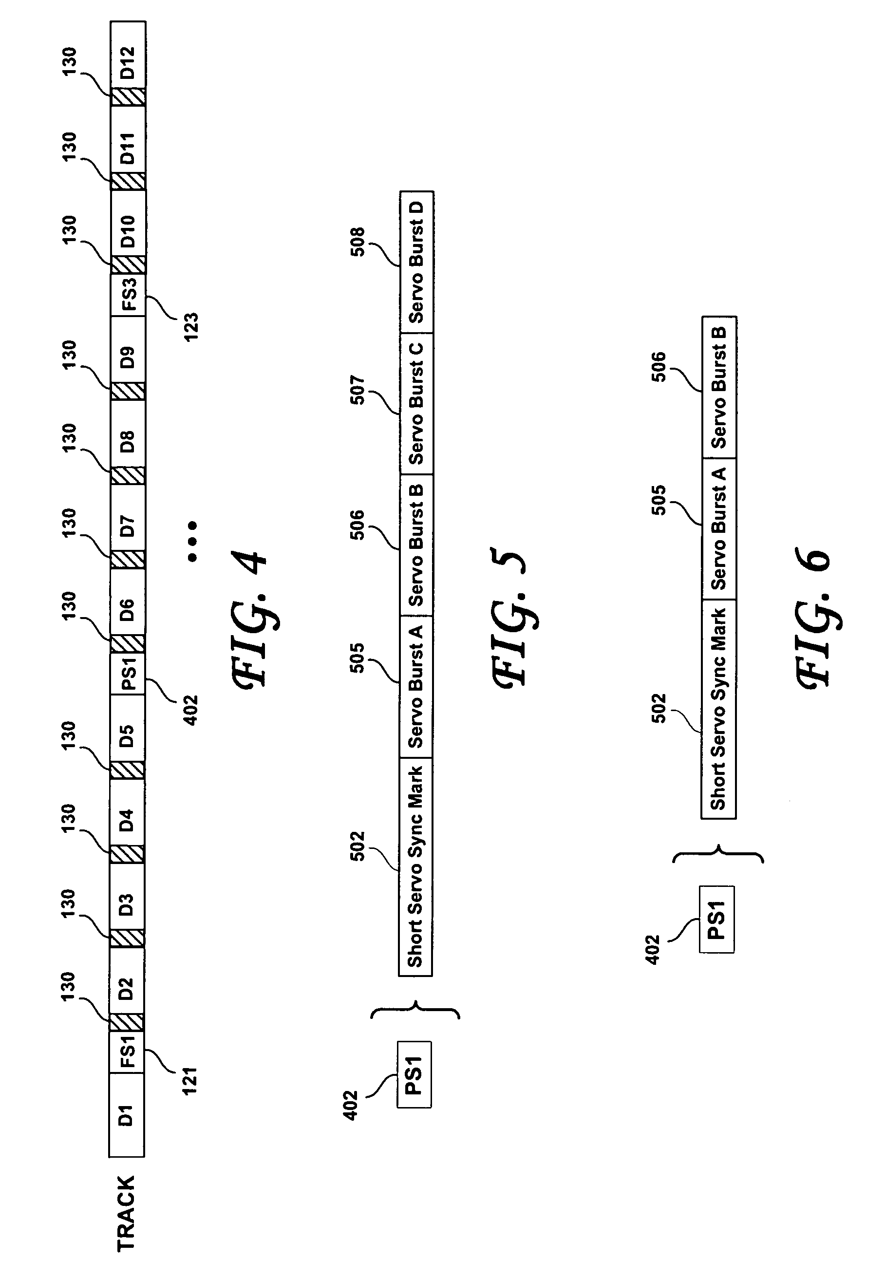
[0026]FIG. 4 is a simplified representation of the structure of a track defined on the recording surface of a disk of a magnetic hard disk drive, according to an embodiment of the present invention. Magnetic structures shown in FIG. 4 that are the same as shown in FIG. 1 are labeled with the same reference numbers. Therefore, the track shown in FIG. 4 includes a plurality of data sectors D1–D12. Interspersed within the data sectors are a plurality of full servo wedges of which FS1121 and FS3123 are shown.

[0027]Considering now the portion of the track of FIG. 4 from reference numeral 121 to 123, a disk according to an embodiment of the present invention includes a first full servo wedge 121, and a second full servo wedge 123. The first full servo wedge 121 and the second full servo wedge 123 may each include a preamble, a servo sync word, a track ID (and optionally a wedge ID) and a plurality of servo positioning burst fields (also called servo burst herein), as described relative to...


PUM

PropertyMeasurementUnit
lengthaaaaaaaaaa
areasaaaaaaaaaa
angular velocityaaaaaaaaaa

Abstract

A disk drive has a spindle motor, a disk mounted for rotation on the spindle motor, and a head for reading from and writing to the disk. The disk includes a recording surface having a track that includes a first full servo wedge and a second full servo wedge, each of the first full and second full servo wedges defining a leading end and a trailing end and having, between leading and trailing ends, a preamble, a servo sync word, a track ID, and a plurality of servo positioning burst fields. The recording surface further includes user addressable data locations and a first partial servo wedge disposed between the trailing end of the first full servo wedge and the leading end of the second full servo wedge. The first partial servo wedge is devoid of preamble, track ID and wedge ID and includes a short servo sync mark that is different from the servo sync word. The servo sync mark defines a predetermined bit pattern that is immediately followed by a plurality of servo bursts.

Description

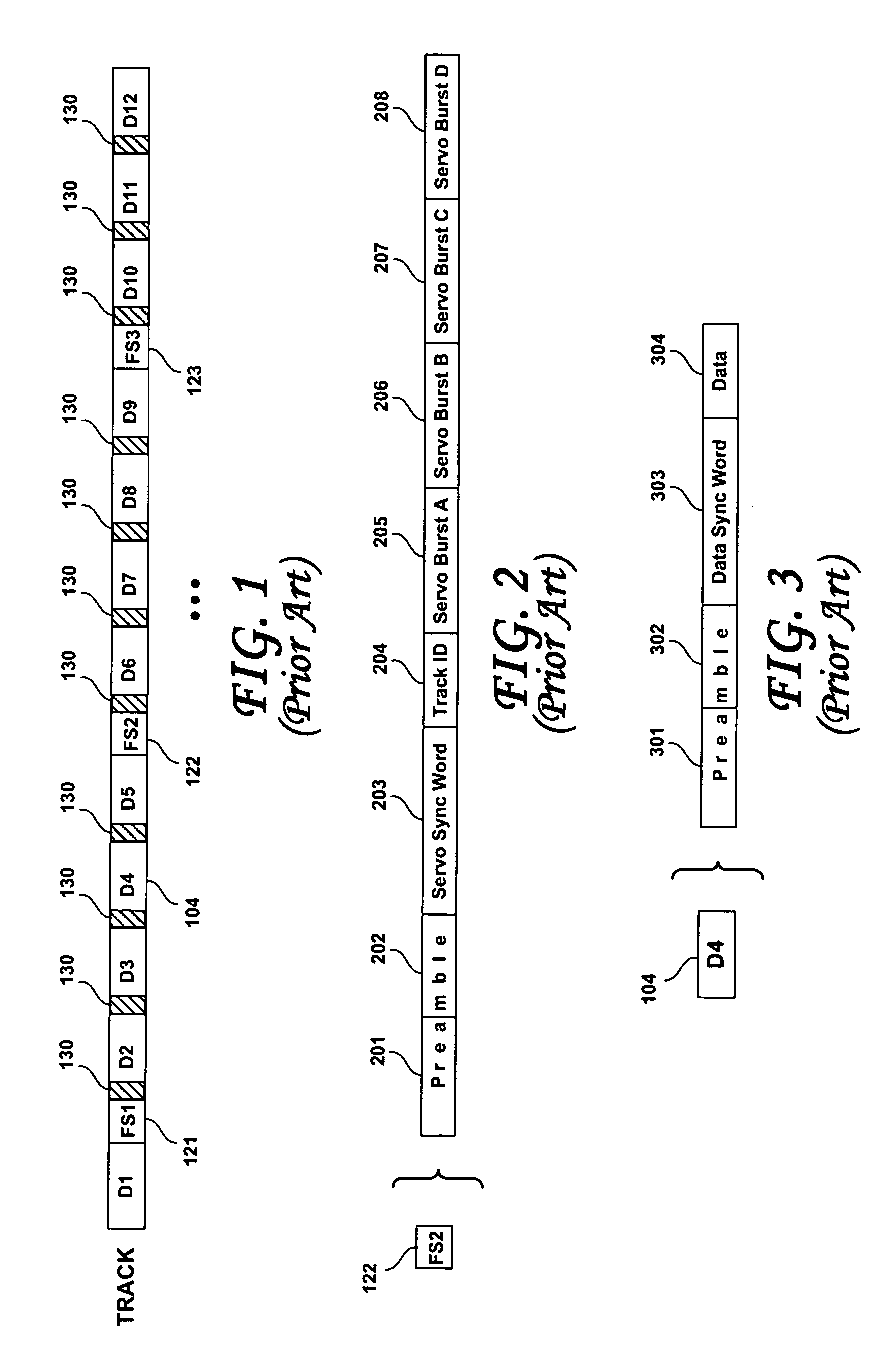
BACKGROUND OF THE INVENTION[0001]1. Field of the Invention[0002]The present invention relates to disk drives. More particularly, the present invention relates to disk drives having a magnetic disk that has one or more partial servo wedges between full servo wedges.[0003]2. Description of the Prior Art[0004]In contemporary magnetic hard disk drives, servo sectors of servo information are interspersed with data sectors circumferentially in concentric tracks around the recording surface or surfaces of the disk or disks. As shown in FIG. 1, the format of a track of a rigid magnetic disk drive calls for regularly spaced embedded servo sectors (also called servo wedges) (of which representative servo sectors 121, 122, 123 are shown) containing servo information therein. Between the embedded servo sectors are a number of data sectors, of which D1–D12 are shown. There may be an integer number of data sectors between any two servo sectors. However, a track may also include a non-integer numb...

Claims


Application Information

Patent Timeline
Patent Type & Authority Patents(United States)
IPC IPC(8): G11B5/09G11B5/596
CPCG11B5/59688
Inventor KUPFERMAN, HANAN
Owner WESTERN DIGITAL TECH INC
Learn More