Rail bracket mounting system with locking pin

a technology of locking pins and mounting brackets, which is applied in the direction of balustrades, building types, constructions, etc., can solve the problems of insecure or easily disconnected connections, laborious and time-consuming, cuts and abrasions

Inactive Publication Date: 2006-05-23
KROY BUILDING PROD
View PDF58 Cites 38 Cited by
  • Summary
  • Abstract
  • Description
  • Claims
  • Application Information

AI Technical Summary

Problems solved by technology

These fasteners have a small surface area of contact against the piece fastened, resulting in a connection that may be insecure or easily disconnected.
Such fasteners also protrude from the fence and can pose a safety risk by contact with the skin, resulting in cuts and abrasions.
This is laborious and time consuming.
However, the rail is supported internally and without any external support.
This both limits the bracket to use with a hollow rail with an adequately large opening and also places the weight of the rail against the inside of the top wall of the rail.
If additional pressure is placed on the rail, the top wall can fail, requiring the rail to be replaced.
The internal support also interferes with the placement of longitudinal reinforcing structure inside the rail.
It is noteworthy that none of the prior art known to applicant provides a rail bracket system capable of holding the rail in position for attachment to the post, without requiring separate support of the rail to accomplish the attachment.

Method used


Image

  • Rail bracket mounting system with locking pin
  • Rail bracket mounting system with locking pin
  • Rail bracket mounting system with locking pin

Examples


Embodiment Construction

[0020]For the purposes of promoting an understanding of the principles in accordance with the invention, reference will now be made to the embodiments illustrated in the drawings and specific language will be used to describe the same. It will nevertheless be understood that no limitation of the scope of the invention is thereby intended. Any alterations and further modifications of the inventive features illustrated herein, and any additional applications of the principles of the invention as illustrated herein, which would normally occur to one skilled in the relevant art and having possession of this disclosure, are to be considered within the scope of the invention claimed.

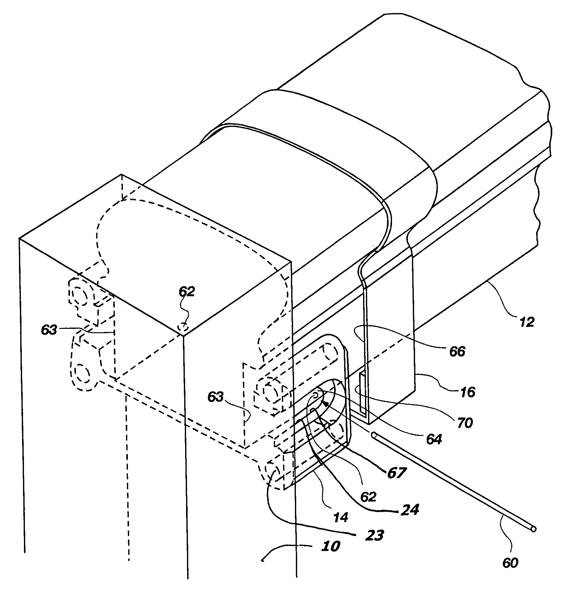
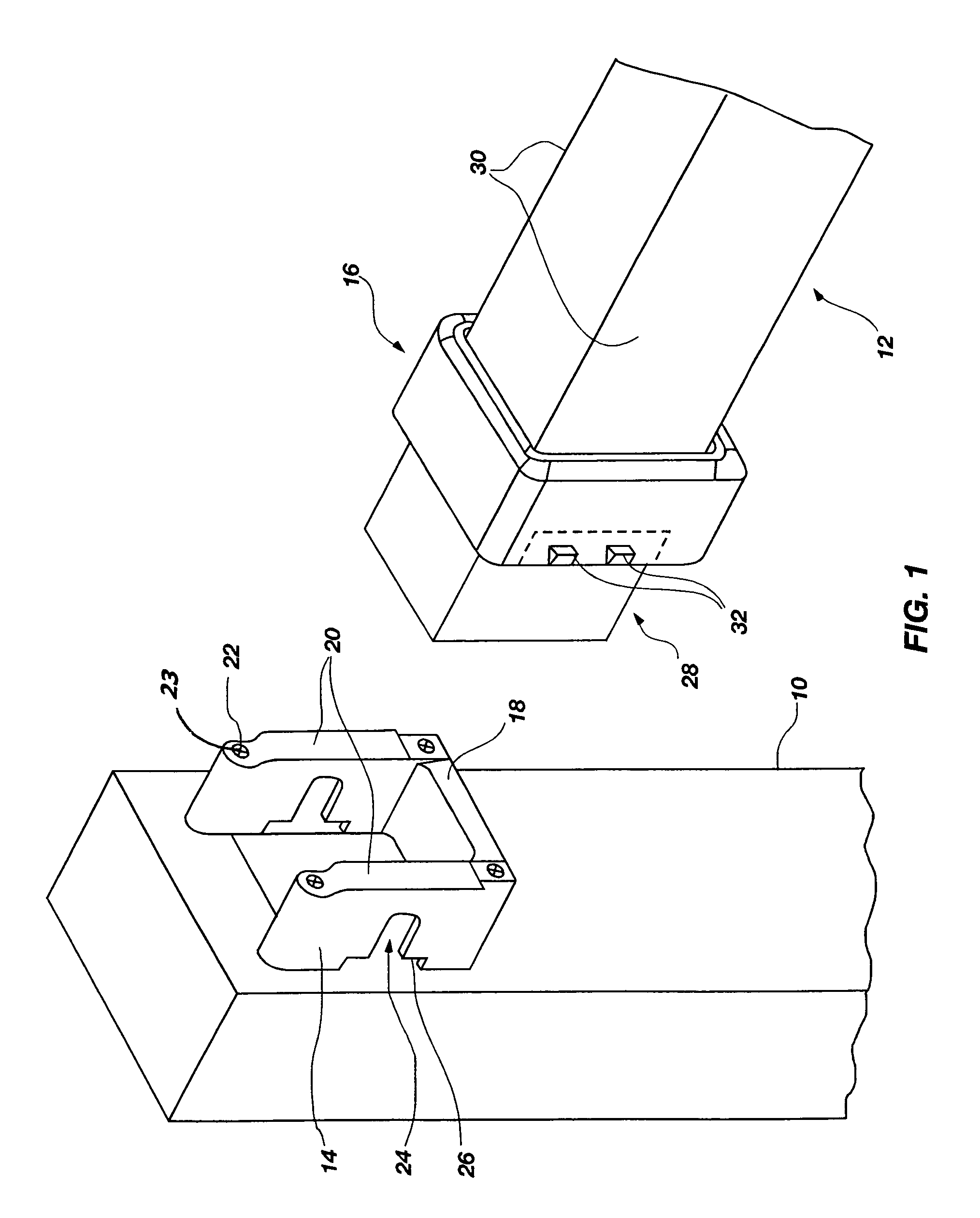
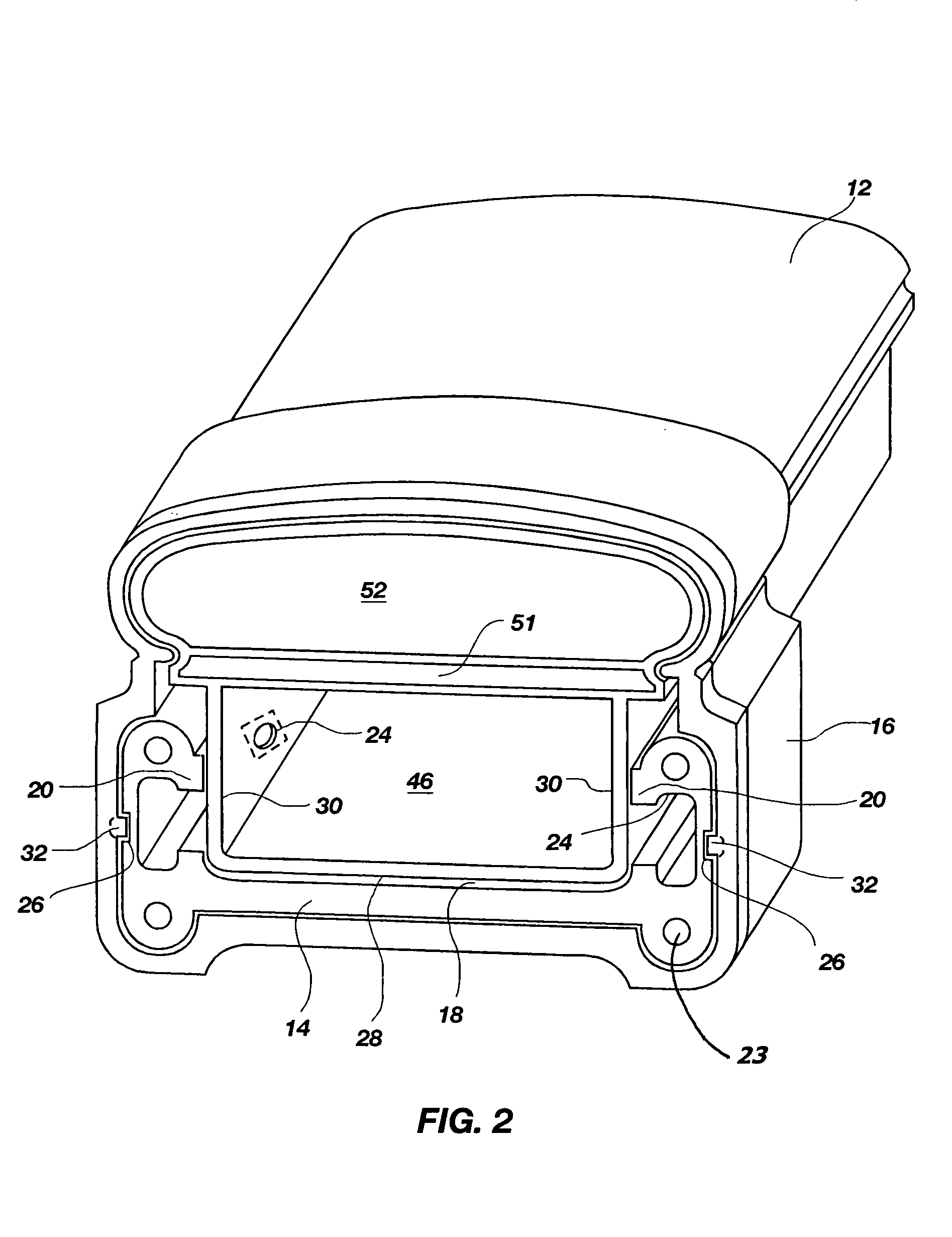
[0021]The invention is directed to a system for attaching fence members together with a bracket. FIGS. 1–3 show some of the possible embodiments of the invention. The support bracket 14 is attached to the post 10, also sometimes referred to herein as a fence rail support. In the embodiment shown in FIG. 1, the...


PUM

PropertyMeasurementUnit
lengthaaaaaaaaaa
widthaaaaaaaaaa
diameteraaaaaaaaaa

Abstract

A rail bracket mounting system, including a bracket that is attached to a post. The bracket is formed to support the notching of a rail. The end of a rail is then nested into the bracket, and is supported by the bracket. The rail is then secured to the bracket by fasteners such as screws, and a cover may then be placed over the bracket, housing the securing fasteners. The rail may be hollow or solid. A hollow rail may be reinforced along its entire length by the insertion of one or more reinforcing members through a hollow portion of the rail.

Description

CROSS-REFERENCE TO RELATED APPLICATIONS[0001]This application is a continuation of U.S. patent application Ser. No. 10 / 039,234, filed Dec. 31, 2001 now abandon, entitled “Rail Bracket Mounting System,” which is incorporated herein by reference in its entirety and which is a continuation of U.S. patent application Ser. No. 09 / 919,502, filed Jul. 31, 2001 now abandon, entitled “Rail Bracket Mounting System,” which is incorporated herein by reference in its entirety and which is a continuation-in-part of U.S. patent application Ser. No. 09 / 844,846, filed Apr. 28, 2001 now abandon, entitled “Rail Bracket Mounting System,” which is incorporated herein by reference in its entirety, including but not limited to those portions that specifically appear hereinafter.STATEMENT REGARDING FEDERALLY SPONSORED RESEARCH OR DEVELOPMENT[0002]Not ApplicableBACKGROUND OF THE INVENTION[0003]1. The Field of the Invention[0004]The present invention relates generally to a rail attachment bracket system, and...

Claims


Application Information

Patent Timeline
Patent Type & Authority Patents(United States)
IPC IPC(8): E04H17/14E04F11/18
CPCE04F11/181E04H17/1421E04H2017/1452Y10T29/49966Y10T29/49838Y10T29/4995Y10T29/49876Y10T29/49625E04H17/1452E04H17/1417E04H17/1488
Inventor QUAINTANCE, RANDY R.WEST, RONALD R.
Owner KROY BUILDING PROD
Why Eureka
Try Eureka