Width and lengthwise direction tape printing control device and program

a control device and tape printing technology, applied in the direction of digital output to print units, instruments, transportation and packaging, etc., can solve the problems of user trouble, multitude of labels to be printed with enormous labor of users, and user inability to insert the plug of the cable into the correct sock

Inactive Publication Date: 2006-05-30
BROTHER KOGYO KK
View PDF28 Cites 15 Cited by
  • Summary
  • Abstract
  • Description
  • Claims
  • Application Information

AI Technical Summary

Benefits of technology

[0011]By the printing control device configured as above, a label having a character string printed thereon in the width direction of the print tape and a label having the character string printed thereon in the lengthwise direction of the print tape can be created by only one character string input and printing operation. Therefore, with the printing control device, two labels that can be suitably stuck on a cylindrical member like a network cable (plug side) and a flat part of a device like a hub into which the network cable is plugged (socket side) can be created with ease.
[0013]By the program configured as above, a label having a character string printed thereon in the width direction of the print tape and a label having the character string printed thereon in the lengthwise direction of the print tape can be created by only one character string input and printing operation. Therefore, with the program, two labels that can be suitably stuck on a cylindrical member like a network cable (plug side) and a flat part of a device like a hub into which the network cable is plugged (socket side) can be created with ease.

Problems solved by technology

However, with the identification label applied on the cable only, the user is not necessarily able to insert the plug of the cable into a correct socket.
However, in order to create the label suitable for being stuck on a cylindrical member like a cable (plug side) and the label suitable for being stuck on a flat part like a part in the vicinity of a socket (socket side) with the tape printing device proposed in the document #2, data editing and printing operation have to be carried out for each of the labels and such work is troublesome to users.
Especially when a great number of cables have to be connected to a line concentrator like a hub, multitudes of labels have to be printed with enormous labor of the user.

Method used


Image

  • Width and lengthwise direction tape printing control device and program
  • Width and lengthwise direction tape printing control device and program
  • Width and lengthwise direction tape printing control device and program

Examples


Embodiment Construction

[0024]Referring now to the drawings, a description will be given in detail of a preferred embodiment in accordance with the present invention.

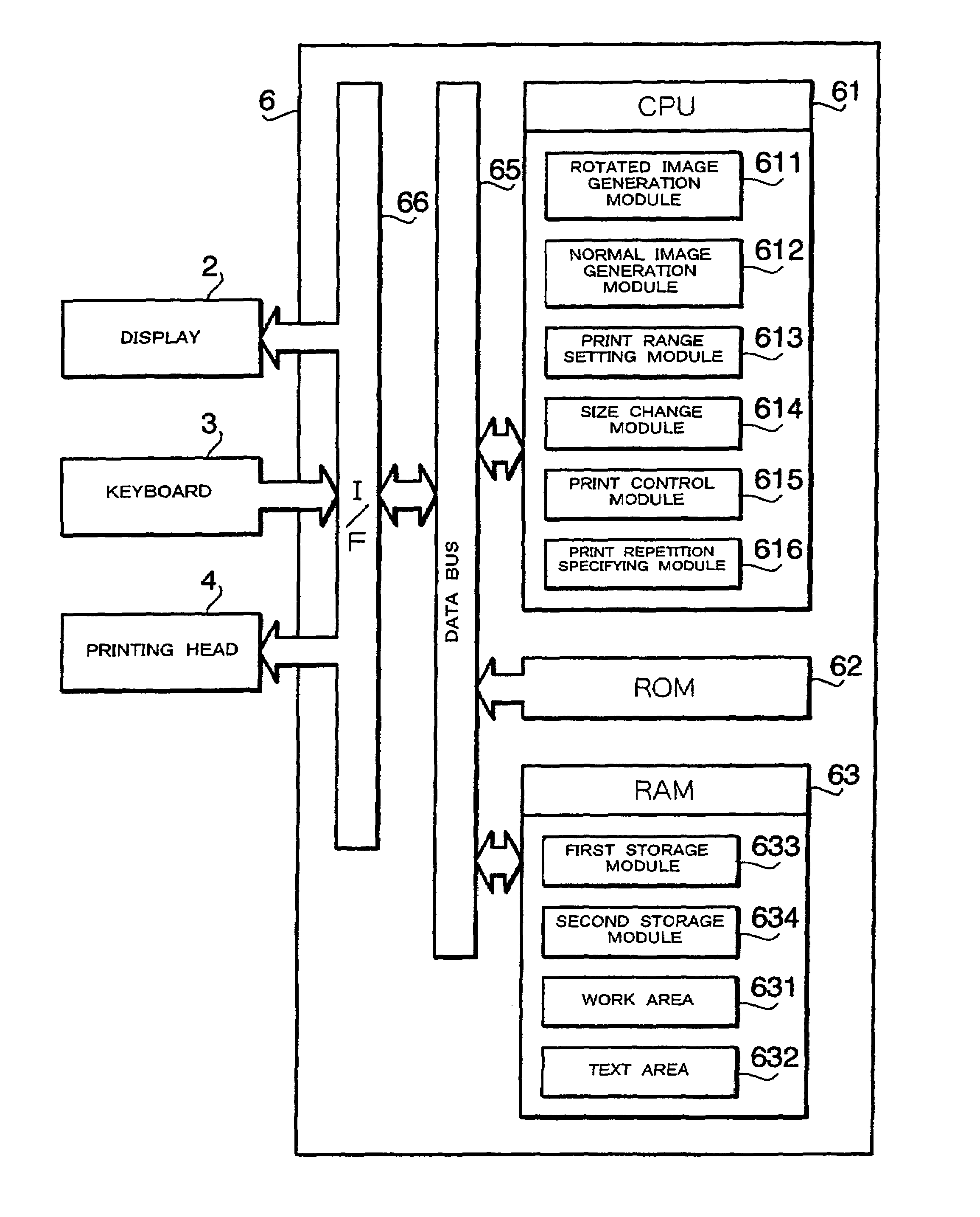
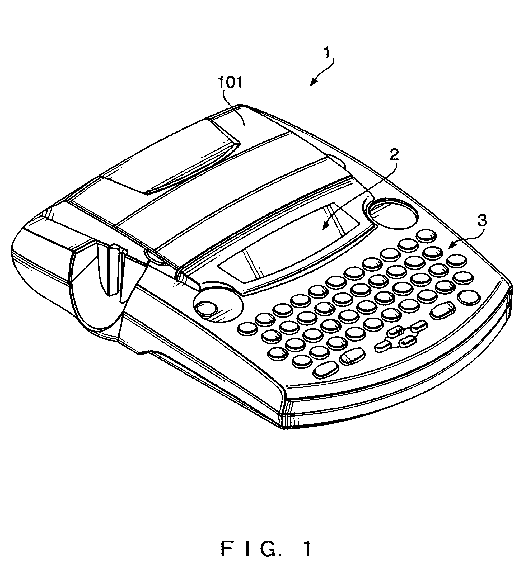
[0025]FIG. 1 is an external view of a tape printing device 1 in accordance with an embodiment of the present invention. As shown in FIG. 1, the tape printing device 1 has a display 2 and a keyboard 3 which are arranged in a front part of its top surface. In the rear part of the tape printing device 1, a cover 101 is formed to be openable and closable. Inside the cover 101, a cassette storage part provided with a printing head 4 (see FIG. 3) is placed.

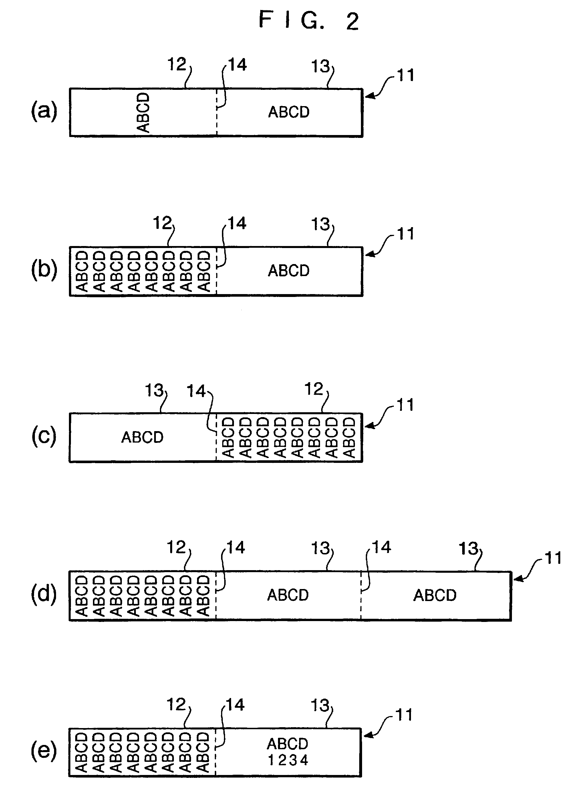
[0026]Print tape, as a print medium for the tape printing device 1, includes a print sheet as a long tape-like print medium (having a print surface (on which characters, symbols, etc. are printed) on its front and an adhesive material layer on its back) and a releasable sheet (having a releasable surface processed with silicone resin, etc.) which are stacked up to be releasable. The print tape is ...


PUM

PropertyMeasurementUnit
widthaaaaaaaaaa
sizesaaaaaaaaaa
sizeaaaaaaaaaa

Abstract

A print image of a character string to be printed on a print tape, rotated counterclockwise from the lengthwise direction of the print tape by 90 degrees to be arranged in the width direction of the print tape, is generated (S450). The print image is repetitively arranged sequentially in the lengthwise direction of the print tape (S470) and thereby label printing is executed (S480). Subsequently (S500), a normal print image of the character string arranged in the lengthwise direction of the print tape is generated (S430) and label printing of the normal print image is executed (S480).

Description

TECHNICAL FIELD[0001]The present invention relates to a tape printing device and a program which are used for printing a character string on a tape-like print medium.BACKGROUND OF THE INVENTION[0002]Tape printing devices, capable of printing a character string on a print tape made of an adhesive print sheet (with an adhesive agent previously applied on its back) and a releasable sheet which are bonded together to be releasable, are well known. The tape printing devices of this type are widely used for office use, home use, etc. because of their high usability allowing users to print a title, caption, etc. on the surface of a print sheet easily and beautifully. After printing a title, caption, etc. on the print tape, a user peels the print sheet away from the releasable sheet and sticks the print sheet (i.e. a label) on the spine of a file, videotape, etc.[0003]Meanwhile, with the progress of computers and network technologies of recent years, there are many situations where numbers ...

Claims


Application Information

Patent Timeline
Patent Type & Authority Patents(United States)
IPC IPC(8): B41J11/26B41J5/30B41J3/36B41J11/00B41J3/407B41J5/00B41J21/00G06F3/12
CPCB41J11/008B41J3/4075
Inventor UENO, HIDEOMORI, MASAHARUITAKURA, JUNITO, TAKEO
Owner BROTHER KOGYO KK
Why Eureka
Try Eureka