
Electrical connector with a locking mechanism

Active Publication Date: 2006-05-30
J S T CORP
View PDF4 Cites 24 Cited by
  • Summary
  • Abstract
  • Description
  • Claims
  • Application Information

AI Technical Summary

Problems solved by technology

In recent years, electronic systems have grown increasingly complicated.

Method used


Image

  • Electrical connector with a locking mechanism
  • Electrical connector with a locking mechanism
  • Electrical connector with a locking mechanism

Examples


Embodiment Construction

[0022]The invention is described with reference to an exemplary embodiment illustrated in the attached drawings and made in accordance with a corresponding method of the invention.

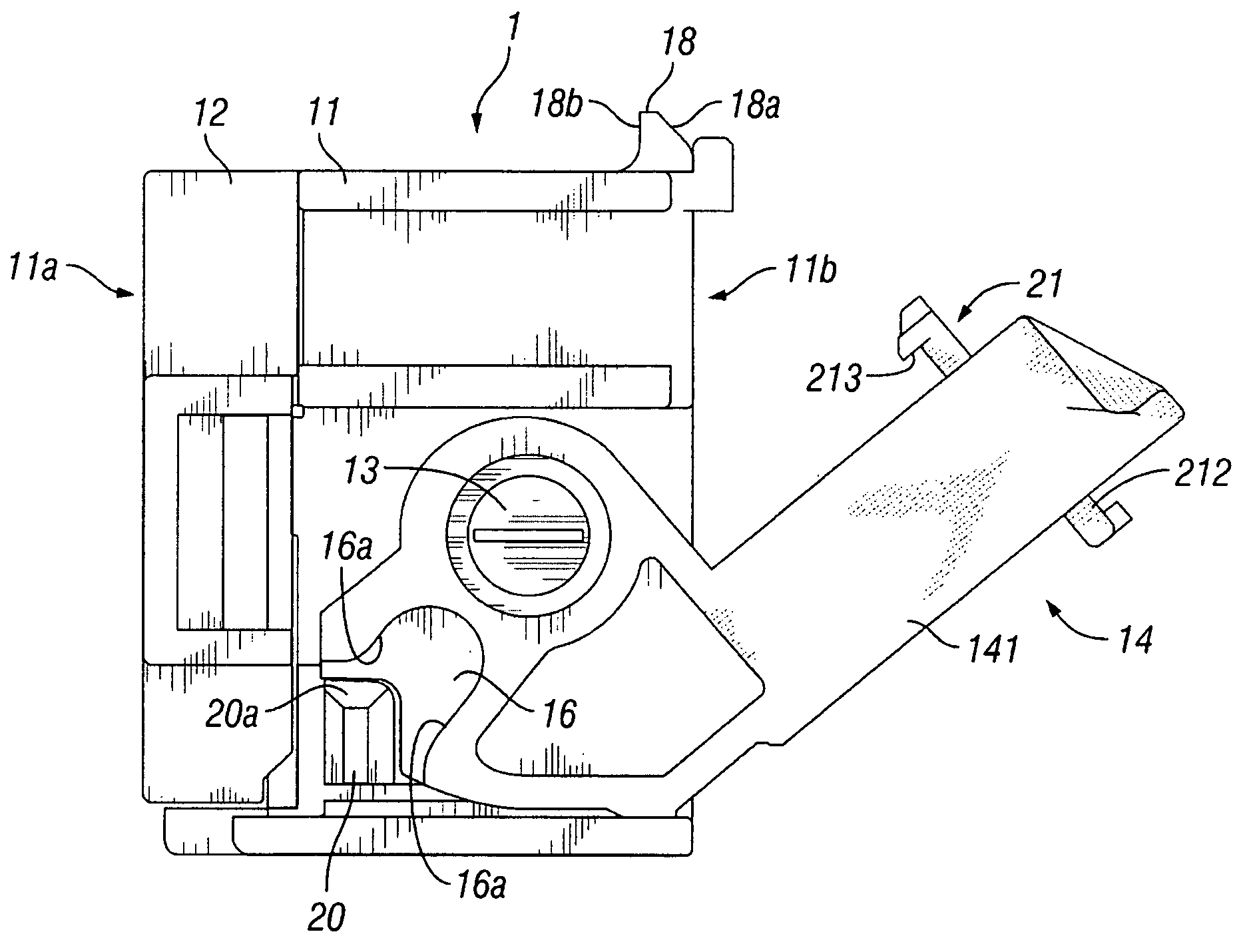
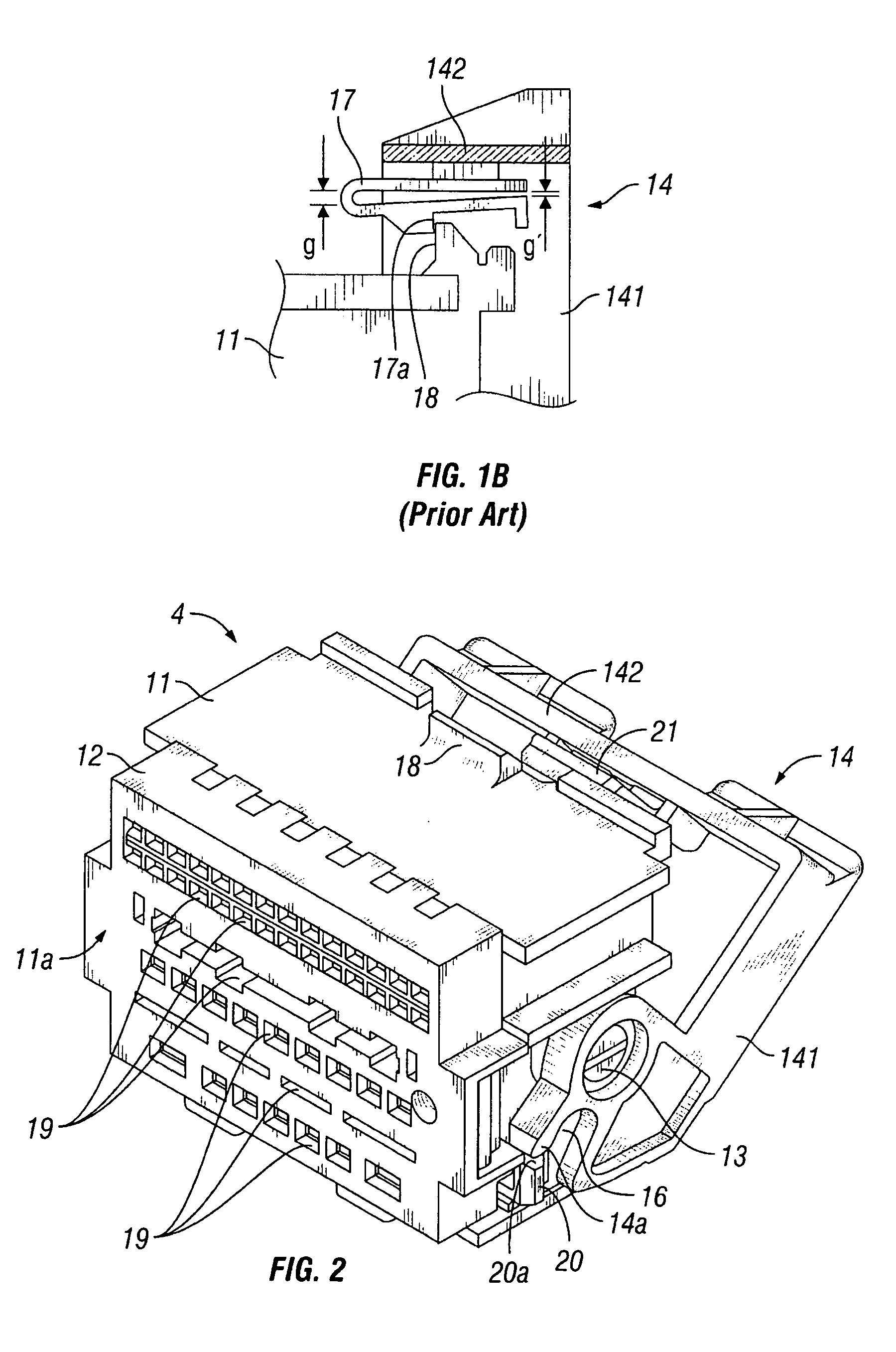
[0023]FIGS. 2 and 3 illustrate an electrical connector according to one embodiment of the invention. Referring to FIG. 2, a female connector 1 is shown as including a female housing 11 with a lever-type connector locking mechanism 14. The connector 1 is typically manufactured by a connector manufacturer, and thereafter supplied to a harness assembler to attach wiring harnesses thereto. The connector 1 can be connected with a mating connector, i.e., a male connector, to electrically interconnect wiring harnesses. The dimensions of the housing 2 is determined to a large extent by the size and number of the terminals or poles.

[0024]The housing 11 is a single-piece component made of insulating material, such as plastic, using a molding method. The housing 11 may alternatively be formed using other known materi...


PUM


Abstract

An electrical connector includes a housing and a lever supported pivotally on at least one pivot disposed on the housing. The lever rotates on the pivot within a range from a pre-engagement position to a final engagement position. The lever also has a recess configured to fit a boss disposed on a mating connector therein in accordance with rotational movement of the lever. Further, the lever includes a connector locking portion disposed on a beam thereof. The connector locking portion includes a base portion extending downward from the beam, a flap portion supported by the base portion and extending in a direction substantially tangent to the rotational movement, and a detent disposed in proximity of a first free end of the flap portion such that the detent engages with an engaging portion disposed on the housing at the final engagement position.

Description

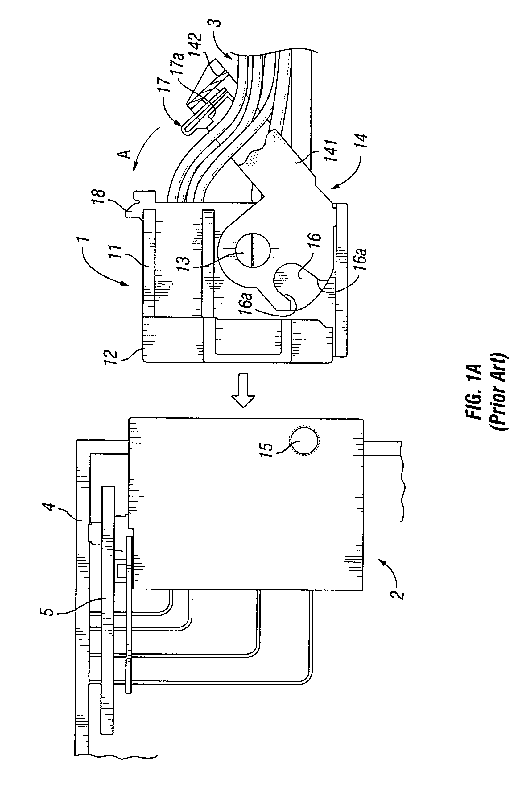
BACKGROUND OF INVENTION[0001]1. Field of the Invention[0002]The invention relates generally to electrical connectors, and particularly to an electrical connector with a locking mechanism that assures a combination with a mating electrical connector.[0003]2. Background Art[0004]An electrical connector is a core component used in many electronic systems to connect wiring harnesses. In recent years, electronic systems have grown increasingly complicated. As a consequence, the number of electrical connectors used in some electronic systems has increased, along with the number of wiring harnesses. Some relatively large connectors have also been developed, which may be provided with several dozen terminals or poles. Such connectors may typically include sub housings or sub connectors corresponding to terminals of various types, such as optical fibers and electrical wires for communication and for power.[0005]Connectors are typically manufactured by a connector manufacturer, and thereafter...

Claims


Application Information

Patent Timeline
IPC IPC(8): H01R13/62
CPCH01R13/62955H01R13/62938H01R13/629H01R13/639
Inventor OSADA, TSUYOSHI
Owner J S T CORP
Learn More