
Parasitic element and PIFA antenna structure

a technology of parametric elements and antenna structures, applied in the field of radio frequency antennas, can solve the problems and achieve the effect of increasing the size, cost and complexity of cellular phone operations

Inactive Publication Date: 2006-05-30
WI LAN INC
View PDF8 Cites 64 Cited by
  • Summary
  • Abstract
  • Description
  • Claims
  • Application Information

AI Technical Summary

Benefits of technology

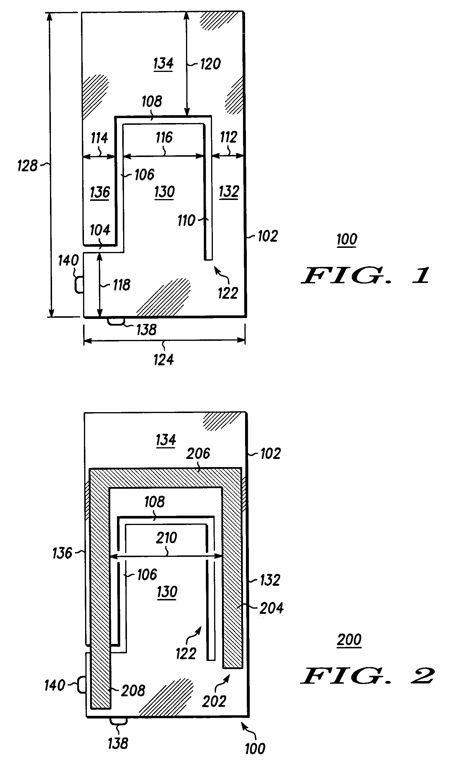
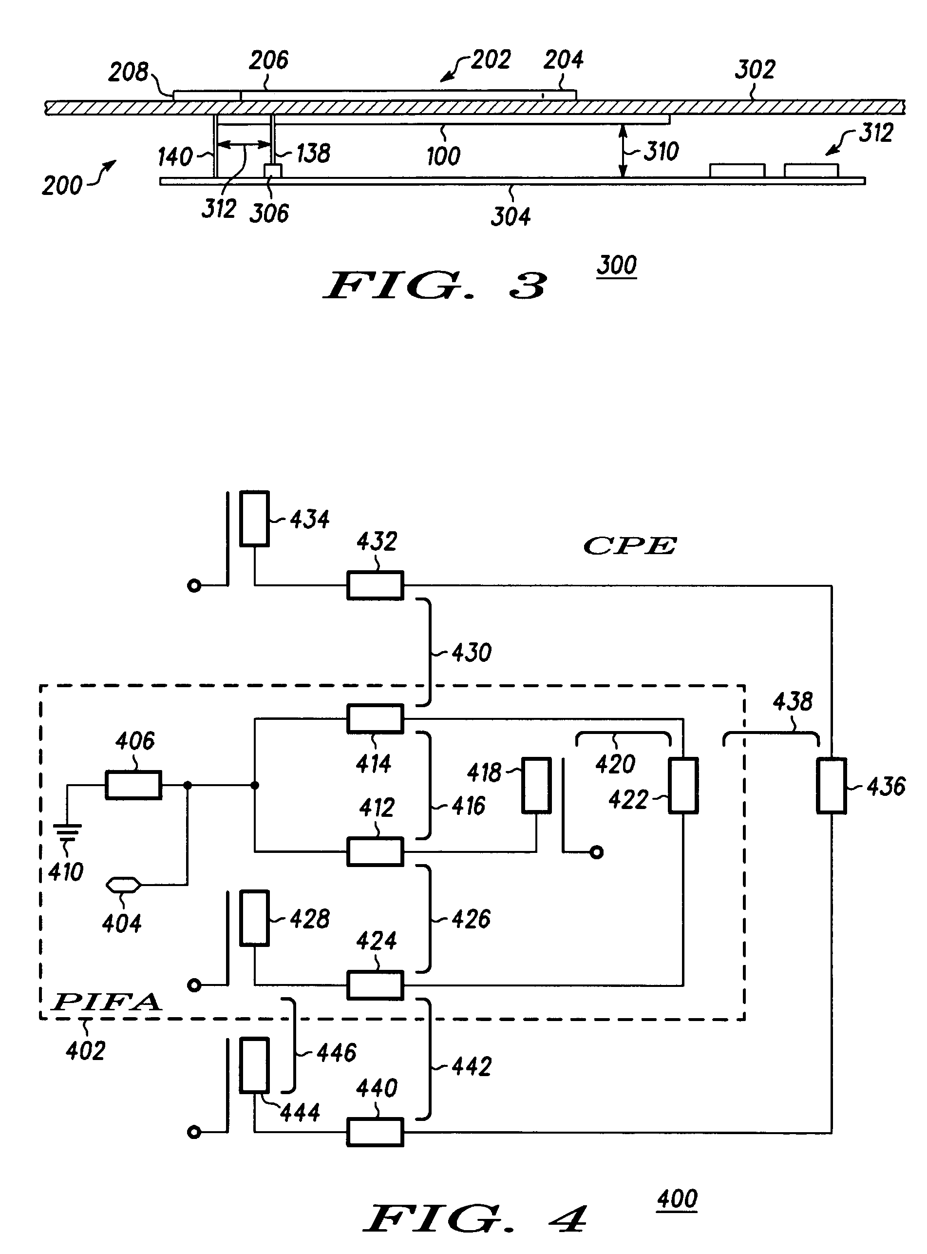
"The present invention is about an antenna that has two parts, a PIFA and a parasitic element. The parasitic element is near the PIFA and helps to transfer RF energy between them. The parasitic element also causes additional radiation in other frequency bands. This design helps to improve the performance of the antenna."

Problems solved by technology

This increases the size, cost and complexity of cellular phones that operate in these two cellular bands and that are required to receive GPS signals.

Method used


Image

  • Parasitic element and PIFA antenna structure
  • Parasitic element and PIFA antenna structure
  • Parasitic element and PIFA antenna structure

Examples


Embodiment Construction

[0016]As required, detailed embodiments of the present invention are disclosed herein; however, it is to be understood that the disclosed embodiments are merely exemplary of the invention, which can be embodied in various forms. Therefore, specific structural and functional details disclosed herein are not to be interpreted as limiting, but merely as a basis for the claims and as a representative basis for teaching one skilled in the art to variously employ the present invention in virtually any appropriately detailed structure. Further, the terms and phrases used herein are not intended to be limiting but rather to provide an understandable description of the invention.

[0017]The terms “a” or “an”, as used herein, are defined as one or more than one. The term plurality, as used herein, is defined as two or more than two. The term another, as used herein, is defined as at least a second or more. The terms including and / or having, as used herein, are defined as comprising (i.e., open ...


PUM


Abstract

A Parasitic Element (202) for use in combination with a Planer Inverted “F” Antenna (PIFA) (100) that creates an additional band of efficient operation for the combined antenna structure (200). The parasitic element (202) is able to be made to conform to surfaces (704) that are near the PIFA, such as of a case (704) of a cellular telephone (706). The parasitic element (202) is positioned so as to radiantly couple with the PIFA (100) in order to create the additional band of efficient operation. A parasitic element (202) is used with a dual band PIFA that operates in two RF bands, such as in the region near 800 MHz and 1.9 GHz, and adds a third band such as in the region near 1.575 GHz to support reception of Global Positioning System signals. This parasitic element (202) can conform to a case (704) of the cellular telephone (706).

Description

FIELD OF THE INVENTION[0001]The present invention generally relates to the field of radio frequency antennas and more particularly to compact, multiple band antennas.BACKGROUND OF THE INVENTION[0002]Radio communications devices are increasingly being used to communicate through and process RF signals within multiple RF bands. An example of multiple RF band devices is a device that is able to communicate in one of several cellular telephone bands, such as the 800 MHz band and the 1.9 GHz Cellular telephone band, while receiving Global Positioning System (GPS) signals in the region of 1.575 GHz. It is often desirable, especially in small and / or portable devices, to minimize the number of antennas that are used on the device, and using a single antenna to cover multiple bands generally provides savings in size and manufacturing cost.[0003]One antenna design used in cellular telephones that operate within two RF bands is a Planar Inverted “F” Antenna (PIFA). A PIFA is able to efficientl...

Claims


Application Information

Patent Timeline
Patent Type & Authority Patents(United States)
IPC IPC(8): H01Q1/24H01QH01Q1/36H01Q5/00H01Q5/371H01Q5/378H01Q9/04
CPCH01Q1/243H01Q1/36H01Q5/378H01Q9/0421H01Q5/371H01Q9/0414
Inventor PONCE DE LEON, LORENZO A.KROEGEL, ROBERT A.
Owner WI LAN INC
Learn More