Loudspeaker device

Inactive Publication Date: 2006-06-06
PANASONIC CORP
View PDF6 Cites 134 Cited by
  • Summary
  • Abstract
  • Description
  • Claims
  • Application Information

AI Technical Summary

Benefits of technology

[0008]A loudspeaker device comprises: an amplifier for receiving an input signal; a loudspeaker unit for reproducing an output signal supplied from this amplifier; a cabinet incorporated with this loudspeaker unit; a microphone for detecting an acoustic output supplied from the loudspeaker unit; and a feedback circuit for feeding back an acoustic output signal detected by the microphone to the input of the amplifier. The loudspeaker unit is mounted to an opening in the cabinet

Problems solved by technology

As shown in FIG. 6, in the conventional loudspeaker device, microphone 3 detects an additional acoustic output as resonance occurring in a closed space in cabinet 2, and therefore it is difficult to prevent the device from oscillating.
Even if resonance components

Method used


Image

  • Loudspeaker device
  • Loudspeaker device
  • Loudspeaker device

Examples


Example

Embodiment 1

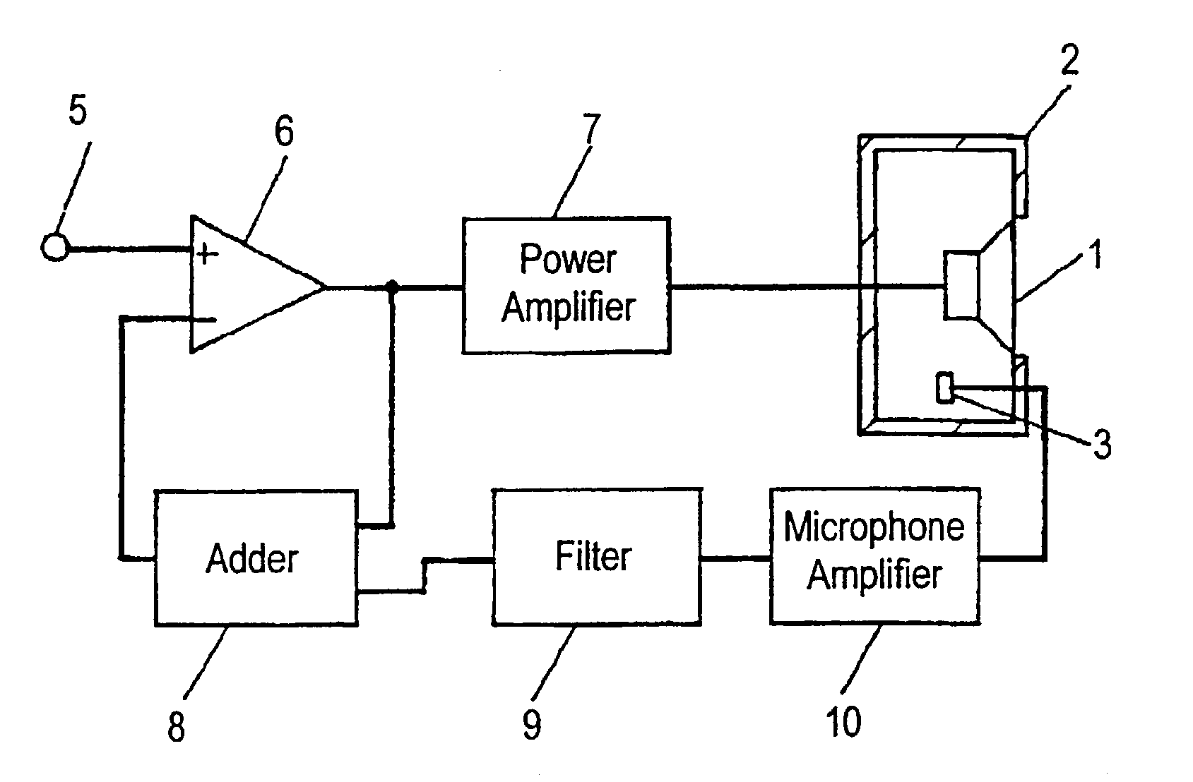
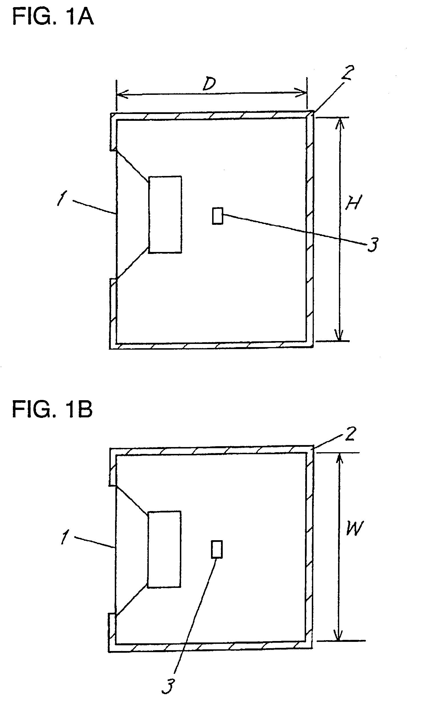
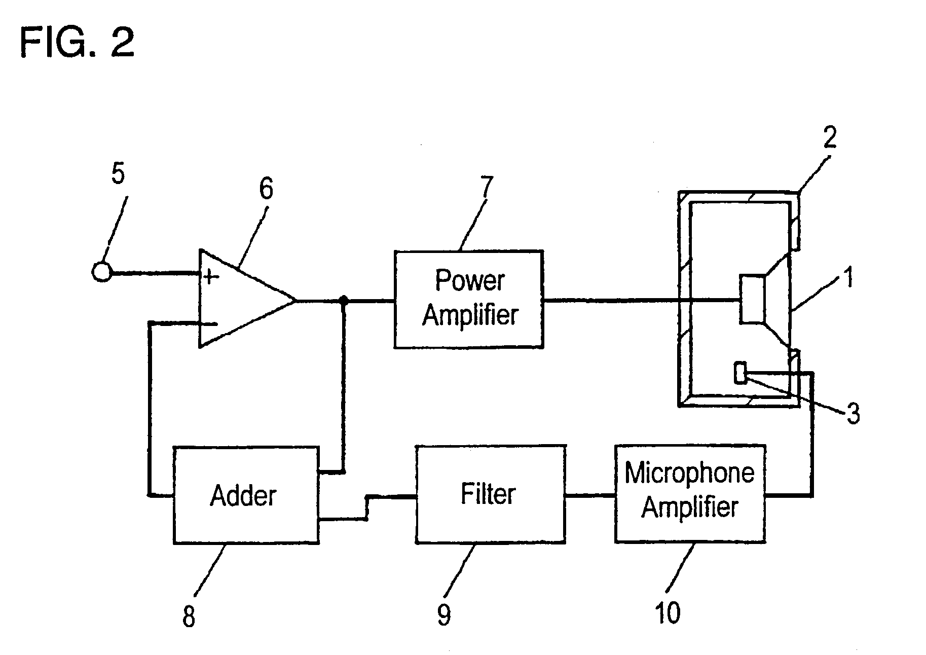
[0019]FIG. 1A is a side sectional view of a loudspeaker device in accordance with embodiment 1 of the present invention, FIG. 1B is an upside sectional view of the loudspeaker device, FIG. 2 is a circuit block diagram of the loudspeaker device, and FIG. 3 shows an acoustic output characteristic of a microphone installed into the loudspeaker device. Loudspeaker unit 1 is mounted to an opening in cabinet 2 having a closed shape and substantially rectangular-parallelepiped shape. Microphone 3 is placed in cabinet 2 through a bracket (not drawn).

[0020]As shown in FIG. 2, the loudspeaker device comprises: input terminal 5; differential amplifier 6; power amplifier 7 receiving an output of differential amplifier 6; microphone amplifier 10 receiving an output of microphone 3 for capturing a sound wave supplied from loudspeaker unit 1; filter 9 for eliminating a standing-wave; and adder for adding the output of differential amplifier 6 to an output of filter 9 and for output it ...

Example

Embodiment 2

[0028]FIG. 4A is a side sectional view of a loudspeaker device in accordance with embodiment 2 of the present invention, and FIG. 4B is an upside sectional view of the loudspeaker device.

[0029]Only a difference from embodiment 1 will be described. The difference is that microphone 3 is mounted to cabinet 2 with bracket 4.

[0030]If bracket 4 is designed appropriately, microphone 3 can be mounted to any position without constraints in cabinet 2. In addition, cabinet 2 is not required to have a complex structure for mounting microphone 3, and therefore, a resin-molding die of cabinet 2 is efficiently designed.

[0031]Bracket 4 is mounted in a method such as an integral molding during forming of cabinet 2, molding with the same material especially when strength is not lowered, screw fastening, adhesion, and fixing to a printed board constituting a feedback circuit.

[0032]In embodiments 1 and 2, a disposition and an operation of all elements like the loudspeaker unit, the microph...


PUM


Abstract

An anti-oscillation loudspeaker device where a reproduced sound is compensated based on a acoustic signal detected by a microphone and a reproduced band is enlarged is provided. In this loudspeaker device, a microphone is placed near a position where sound pressure of resonance occurring in a closed space for at least one of height, width, and depth of the inside of a cabinet is minimum. An influence of the resonance is restrained, a feedback circuit becomes stable, and a feedback amount increases.

Description

[0001]This application is a U.S. National Phase Application of PCT International Application PCT / JP00 / 008411.TECHNICAL FIELD[0002]The present invention relates to a loudspeaker device used for various video / audio apparatuses, and more particularly to a loudspeaker device that detects a reproduced sound supplied from a loudspeaker unit and compensates the reproduced sound.PRIOR ART[0003]The prior art is described with reference to FIG. 5A, FIG. 5B, and FIG. 6.[0004]FIG. 5A is a side sectional view of a conventional loudspeaker device, FIG. 5B is an upside sectional view of it, and FIG. 6 shows a frequency characteristic of a microphone incorporated into the loudspeaker device.[0005]Loudspeaker unit 1 is mounted to an opening of cabinet 2, and an acoustic output signal is emitted. In cabinet 2, microphone 3 for detecting the acoustic output signal generated from the rear part of loudspeaker unit 1 is disposed in an easy-to-install place close to loudspeaker unit 1. Using the detected ...

Claims


Application Information

Patent Timeline
IPC IPC(8): H04R3/00H04R29/00H04R1/22H04R3/04
CPCH04R3/002
Inventor TANAKA, HIDEKAZU
Owner PANASONIC CORP
Why Eureka
Try Eureka