
Footwear structure and method of forming the same

Inactive Publication Date: 2006-06-13
GEER KENTON D
View PDF117 Cites 30 Cited by
  • Summary
  • Abstract
  • Description
  • Claims
  • Application Information

AI Technical Summary

Problems solved by technology

To date, prior art footwear constructions have failed to successfully combine the essential features of an ideal design.
Prior attempts to create the ideal footwear design have been unsuccessful largely because prior structures have emphasized one of the above-noted features to the detriment of others.
Furthermore, prior attempts to construct an ideal footwear design have failed to consider the importance of other key features such as industrialized construction, style and fashion.
First, such conventional footwear designs are provided with an outsole.
The conventional footwear cushioning components and their positioning within the footwear structures of prior art constructions have several undesirable characteristics.
The footwear midsole and insole components are typically made of various foam and rubber materials which are subjected to repeated application of impact forces and stress which cause compression set, degradation, and fatigue resulting in reduced resiliency and failed cushioning properties.
The midsoles in prior art footwear constructions have several undesirable characteristics.
For example, the consumer at the point of purchase is unable to make an alternative choice in the cushioning characteristics of the midsole without selecting separate footwear designs.
Also, the wearer is unable to replace the midsole component after it has degraded and lost its ability to provide adequate cushioning and support.
In addition, the attachment of the midsole to other components in the footwear structure such as the top surface of the outsole, abutting outsole side wall interior surfaces, and to the formed upper negate the ability of the midsole component to adequately compress, deform, and rebound while providing maximum cushioning.
Another undesirable feature of prior art designs is that the ability of the footwear structure to provide maximum cushioning of the foot structures at the appropriate instant in the gait cycle is negated in prior footwear constructions by the positioning of semi-rigid and rigid structural elements in close proximity to the wearer's foot.
All of these semi-rigid and rigid structural elements negate the performance and cushioning ability of the midsole, and therefore negatively impact user comfort.
This formed structure also negates the performance and cushioning ability of the midsole, to the detriment of user comfort.
Furthermore, prior art midsoles have external surfaces, especially along the side portions thereof, which are exposed to environmental conditions such as heat, cold, water, ultraviolet rays, abrasion from rocks, sand, soil, punctures from sharp pointed objects, and cuts from sharp edged objects.
The environmental conditions contribute to the failure of midsole component cushioning in two main ways: degradation of the midsole cushioning materials, and destruction of the means by which the midsole cushioning component is attached to the footwear structure.
Another undesirable feature of prior art designs is that the thin cushioning insole which is positioned between the top surface of the lasting insole or midsole and the wearer's foot is typically too thin to provide optimal cushioning.
These structures, however, remain encumbered by undesirable characteristics.
Unfortunately, the midsole insert and cushion elements must conform to a matching lift height of the peripheral midsole member.
Thus, the method of construction is complex and inefficient, and does not provide for maximum full perimeter cushioning since the rigid peripheral member is in close proximity to the user's foot.
The structure also has no means of providing for a midsole insert for a raised heel design typically found in dress, casual shoe, and boot constructions, and fails to provide air circulation within the structure.

Method used


Image

  • Footwear structure and method of forming the same
  • Footwear structure and method of forming the same
  • Footwear structure and method of forming the same

Examples


Embodiment Construction

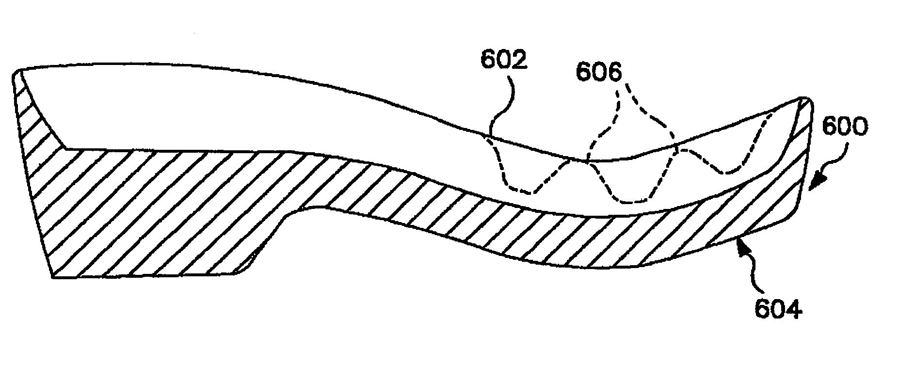
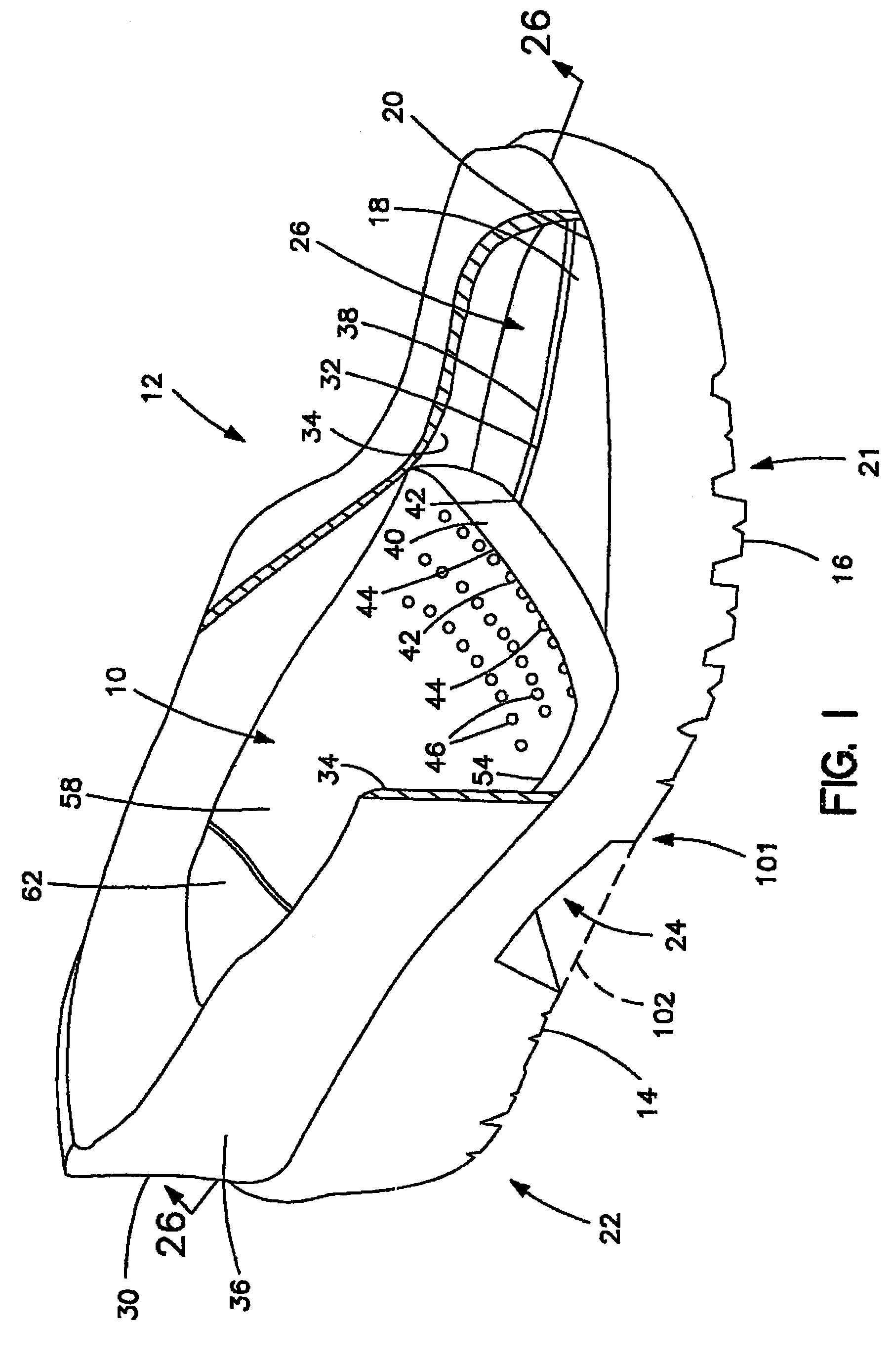
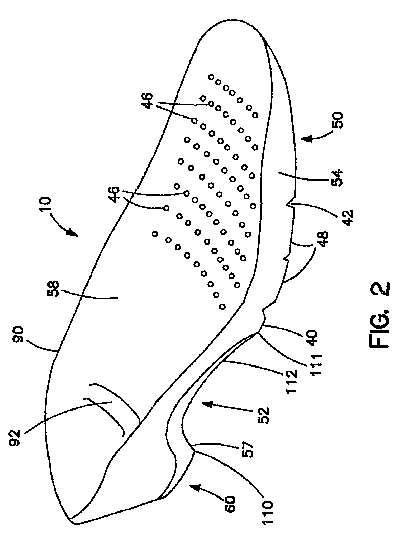
[0098]Referring first to FIG. 1, an isometric view of an exemplary shoe construction according to the invention is shown. An exemplary midsole consistent with the invention is indicated generally at 10. Midsole 10 is shown as combined with an outsole 14 and an upper 30 to form a footwear structure 12 according to the invention. While the upper 30 of the illustrated footwear structure 12 is shown in only outline form, it is to be understood that the invention can be employed in many types of athletic and non-athletic footwear structures such as walking shoes, running shoes, aerobic shoes, casual shoes, boots, ice skates, in-line skates, ski boots, specialty footwear, orthopedic or prescription footwear, etc. Those skilled in the art will recognize that any upper construction could be used with corresponding changes in the outsole design depending on the desired application. Also, a separate upper may not be provided in the case of a molded construction wherein the outsole and the ext...


PUM

PropertyMeasurementUnit
Lengthaaaaaaaaaa
Structureaaaaaaaaaa
Widthaaaaaaaaaa

Abstract

A footwear structure including an outsole, an upper and a midsole. The outsole may include at least one stretch zone for allowing expansion and contraction of the outsole, e.g. corresponding to expansion and contraction of a user's foot during wear. The upper may include stretch zones for allowing expansion of the upper, and the midsole may include varying regions of rigidity.

Description

CROSS-REFERENCE TO RELATED APPLICATIONS[0001]The present application is a continuation of U.S. application Ser. No. 10 / 308,320, filed Dec. 3, 2002, now U.S. Pat. No. 6,701,643 which is a divisional of U.S. application Ser. No. 09 / 609,620 filed Jul. 5, 2000, now U.S. Pat. No. 6,519,876, which is a continuation-in-part of U.S. application Ser. No. 09 / 073,292, filed May 6, 1998, now U.S. Pat. No. 6,092,305, the entire teachings of each of which are incorporated herein by reference.FIELD OF THE INVENTION[0002]The present invention relates in general to footwear structures.BACKGROUND OF THE INVENTION[0003]The ideal footwear design would incorporate the following essential features and characteristics: comfort, cushioning, shock absorption, stability, flexibility, support, good fit, and would also be lightweight. These features are achieved in, and are dependent upon, the structural and functional design elements of the footwear, which enhance the wearer's ability to perform various activ...

Claims


Application Information

Patent Timeline
IPC IPC(8): A43B7/08A43B13/14A43B13/18A43B13/36A43B13/42
CPCA43B1/0081A43B3/26A43B7/06A43B17/08A43B13/187A43B13/36A43B13/42A43B13/14
Inventor GEER, KENTON D.TROY, GARY J.
Owner GEER KENTON D
Learn More