Double-disk assembly for a cigar or cigarette lighter

a double-disk and cigar lighter technology, which is applied in the direction of vehicle arrangement, transportation and packaging, lighting and heating apparatus, etc., can solve the problems of difficult to provide controlled upper and lower limits of temperature window for bimetallic disk operation, and the lighter to pop up

Inactive Publication Date: 2006-06-13
CASCO PRODUCTOS CORP
View PDF11 Cites 2 Cited by
  • Summary
  • Abstract
  • Description
  • Claims
  • Application Information

AI Technical Summary

Benefits of technology

[0006]The periphery of the metal disk is mounted to the lighter structure

Problems solved by technology

A problem with this construction is that the single bimetallic disk 146 is used to cause the lighter to pop-up when the heating element reaches a desired temperature.
The p

Method used


Image

  • Double-disk assembly for a cigar or cigarette lighter
  • Double-disk assembly for a cigar or cigarette lighter
  • Double-disk assembly for a cigar or cigarette lighter

Examples


Embodiment Construction

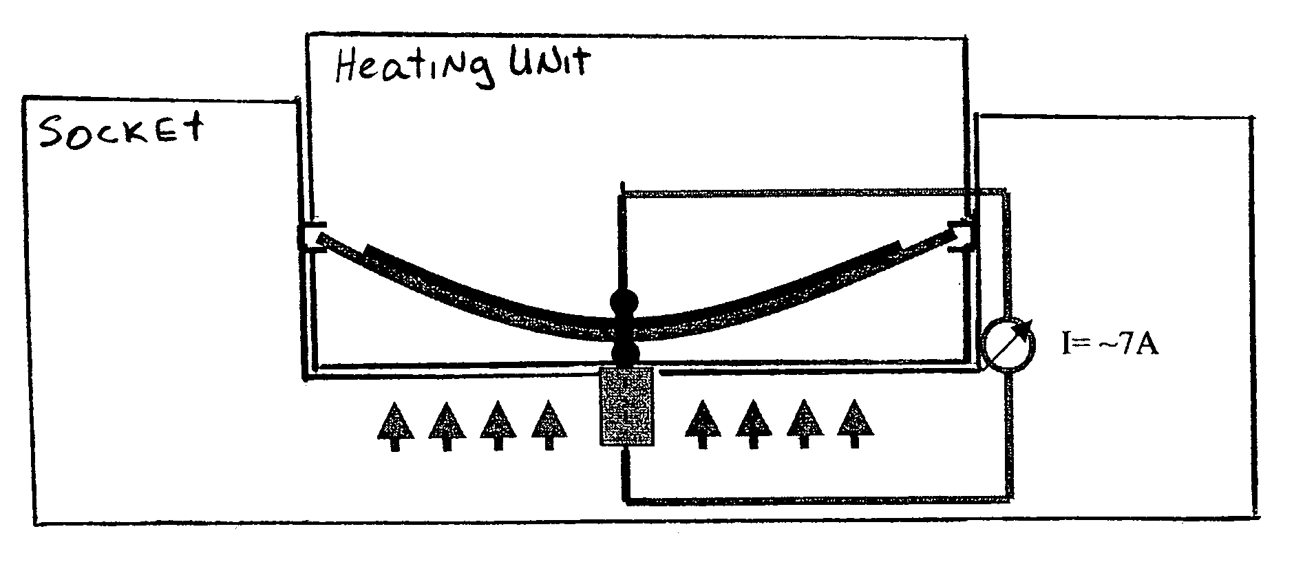
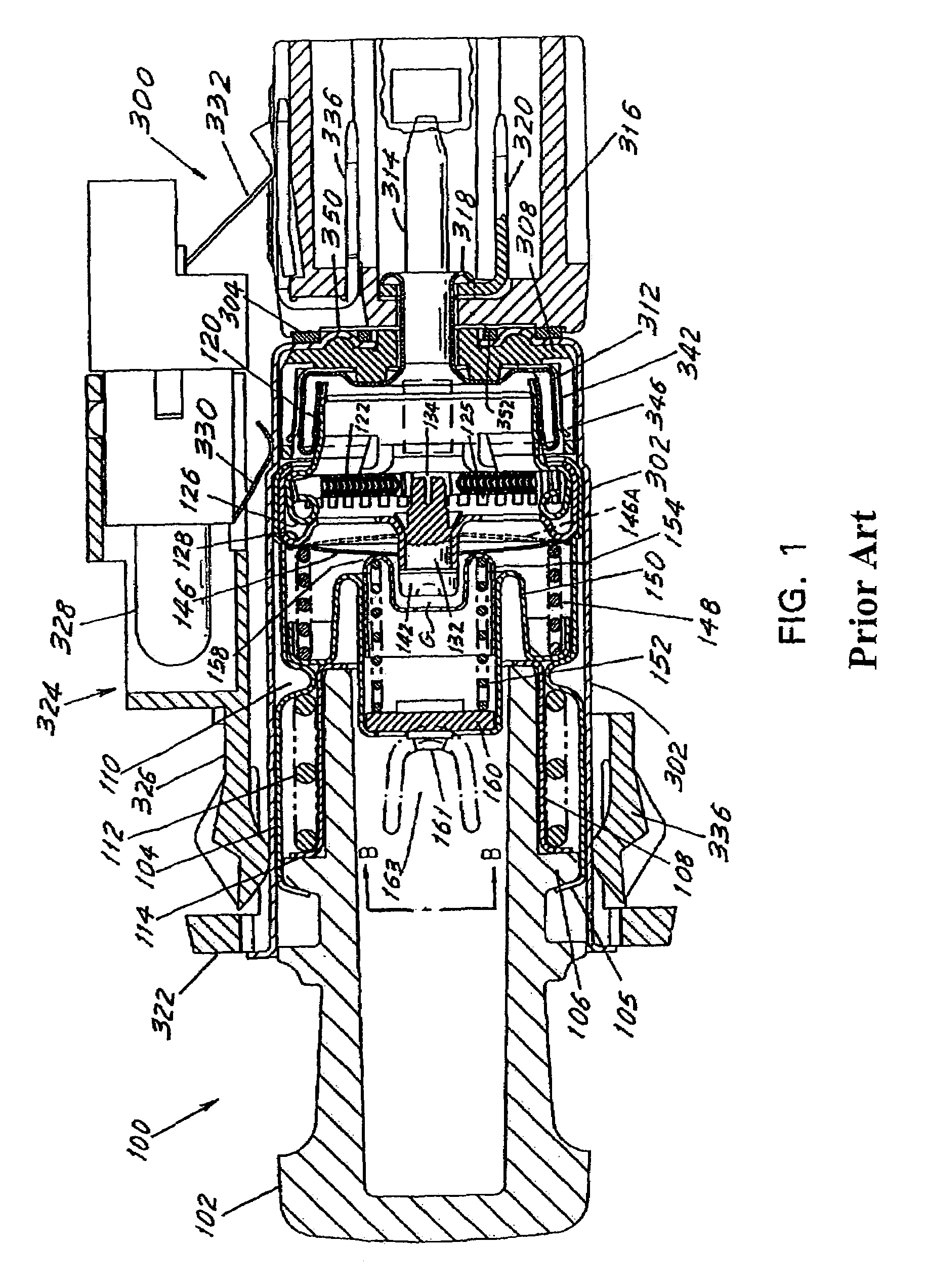
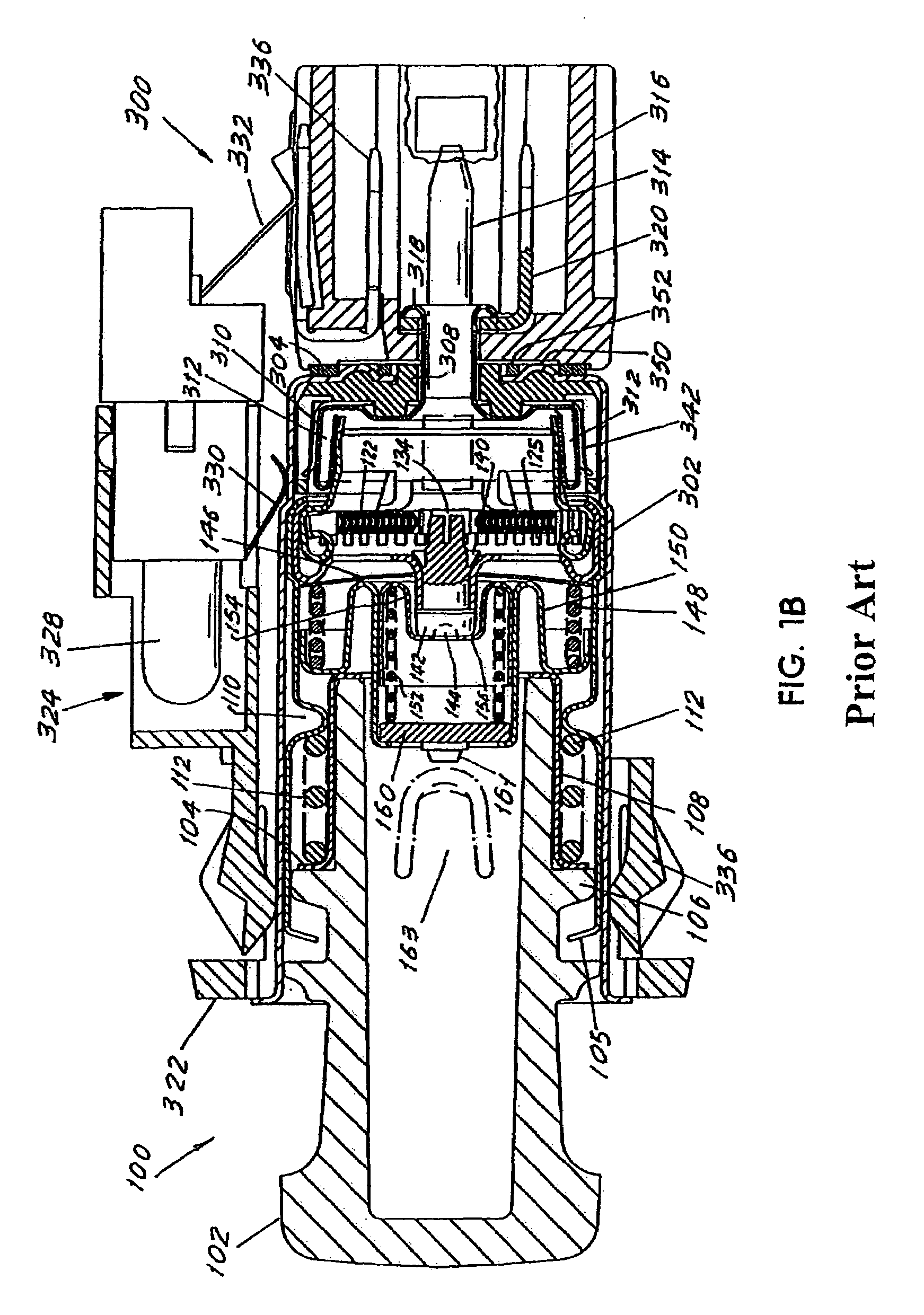
[0014]As previously mentioned, FIGS. 1 and 1B show the components of a prior art electric cigar lighter for an automobile.

[0015]FIGS. 2–5 show the two disk assembly of the present invention. The two disk assembly of the present invention would be substituted for the element 146 shown in FIGS. 1 and 1B. Of course, FIGS. 1 and 1B are only an example of one type of cigar lighter in which the invention can be used. The specific components, other than the double disk element are not of concern in the presently claimed invention and can be modified as within the purview of those skilled in the art.

[0016]As shown in FIG. 2, the double element assembly of the present invention includes a bimetallic disk 1 and a metal disk 2. The metal disk 2 is dome-shaped and the bimetallic disk 1 has an inverted dome shape. The disks 1, 2 are connected to the other by a rivet 3. It is understood that any type of connection is possible which allows the two disks to be connected only at their apex region an...


PUM


Abstract

A double-element assembly for a cigar lighter, having a bimetallic disk, and a metal disk that is not bimetallic, the disks being riveted to one another in a center region of each disk.

Description

BACKGROUND OF THE INVENTION[0001]The present invention relates to a heating element of a cigar lighter, and more particularly to a thermally controlled switching element in a cigar or cigarette lighter.[0002]Various lighters are known for automotive applications, including lighters shown in the following U.S. Pat. Nos. 4,168,422; 4,204,109; 4,207,455; 4,177,374; 5,998,763; and 4,230,931. U.S. Pat. No. 6,740,850 discloses an electric cigar lighter assembly that has a lighter heating assembly 100 that plugs into a socket assembly 300. The lighter assembly 100 includes a heating element 122 and a switch. The switch is comprised of contacts 142 and 154. FIG. 1 shows the lighter assembly 100 inserted into the socket 300 but un-energized because the contacts 142, 154 are not in electrical contact. When the knob 102 is pushed in, thus forcing the lighter 100 into the socket assembly 300 further, the contacts 142, 154 engage in the heater 122 is electrically energized. After a period of tim...

Claims


Application Information

Patent Timeline
IPC IPC(8): F23Q7/00
CPCB60N3/14F23Q7/00H01H37/66
Inventor LAUER, RALPH
Owner CASCO PRODUCTOS CORP
Why Eureka
Try Eureka