
Chemical, biological, radiological, and nuclear weapon detection system comprising array of spatially-disparate sensors and surveillance equipment

a detection system and spatial dispersion technology, applied in the field of civil defense, can solve the problems of government failing to inform the public, etc., and achieve the effect of gaining and maintaining quickly and accurately informing the public, and losing the respect and confidence of the citizenry

Active Publication Date: 2006-06-13
LOCKHEED MARTIN CORP
View PDF5 Cites 4 Cited by
  • Summary
  • Abstract
  • Description
  • Claims
  • Application Information

AI Technical Summary

Benefits of technology

[0005]One way that the government earns and maintains the respect and confidence of the citizenry is by quickly and accurately informing the public when an attack has occurred and by taking the appropriate action. This means that there are two ways in which the government can lose the respect and confidence of the citizenry. First, the government can fail to inform the public when an actual attack has occurred, and second, the government can inform the public that an attack has occurred when in fact there has been so such attack. Therefore, it's important for the government to inform the public of an attack when an attack has in fact occurred, but that it is also important for the government not to issue false alarms. To this end, the respect in the government is best enhanced by a chemical, biological, radiological, and nuclear weapon detection system that both: (1) quickly issues an alarm in the event of a real attack, and (2) accurately withholds false alarms.

Problems solved by technology

This means that there are two ways in which the government can lose the respect and confidence of the citizenry.
First, the government can fail to inform the public when an actual attack has occurred, and second, the government can inform the public that an attack has occurred when in fact there has been so such attack.

Method used


Image

  • Chemical, biological, radiological, and nuclear weapon detection system comprising array of spatially-disparate sensors and surveillance equipment
  • Chemical, biological, radiological, and nuclear weapon detection system comprising array of spatially-disparate sensors and surveillance equipment
  • Chemical, biological, radiological, and nuclear weapon detection system comprising array of spatially-disparate sensors and surveillance equipment

Examples


Embodiment Construction

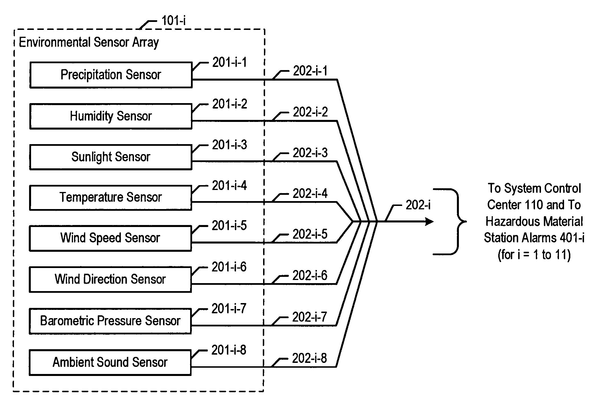
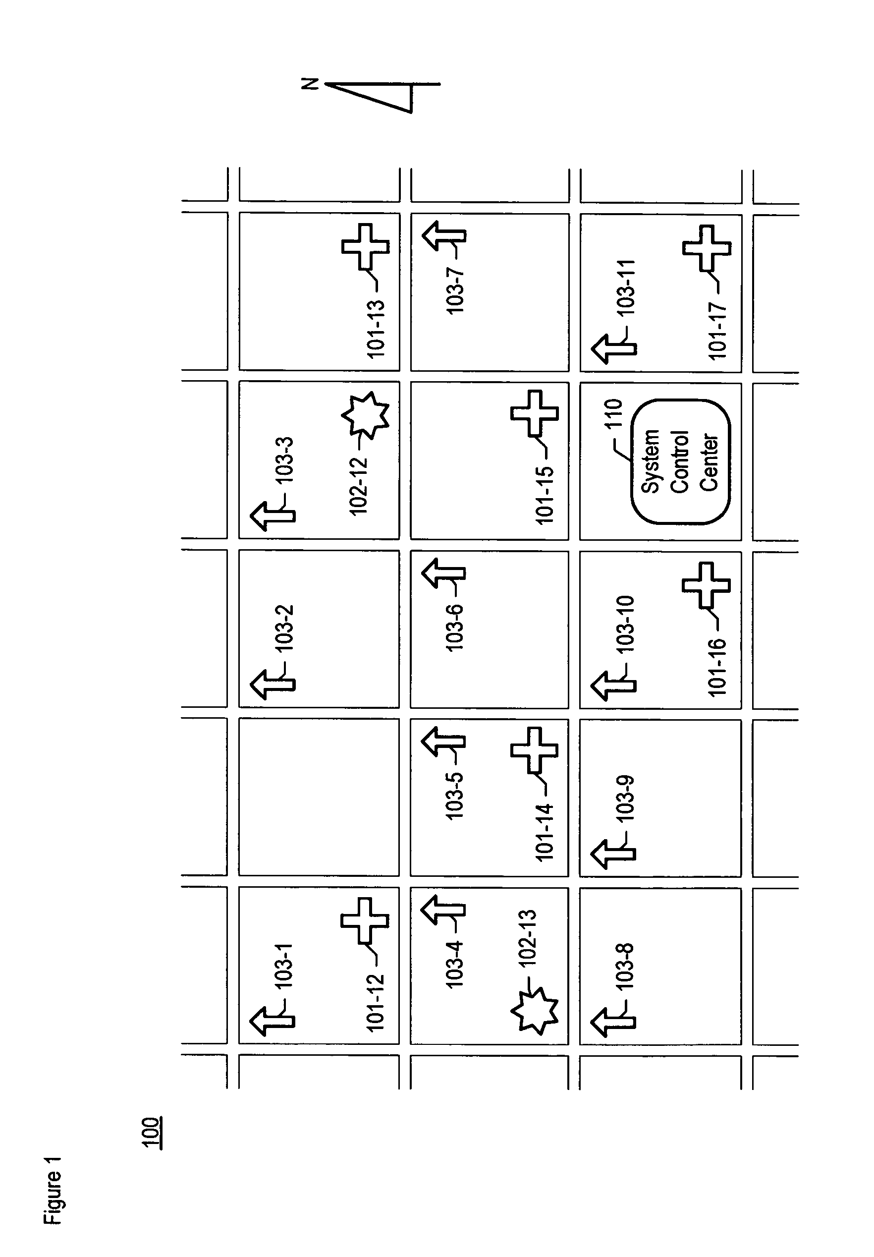
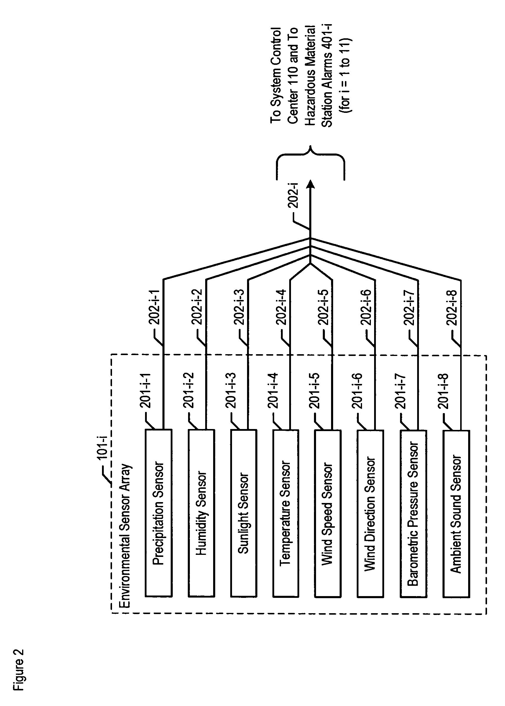
[0020]FIG. 1 depicts a city map and the location of the salient components of the illustrative embodiment of the present invention on that map. The illustrative embodiment comprises:[0021]i. seventeen (17) spatially-disparate environmental sensor arrays 101-1 through 101-17,[0022]ii. thirteen (13) spatially-disparate video camera clusters 102-1 through 102-13,[0023]iii. eleven (11) spatially-disparate hazardous material detection stations 103-1 through 103-11, and[0024]iv. system control center 110.

Environmental sensor arrays 101-1 through 101-11 and video camera clusters 102-1 through 102-11 are not distinctly shown in FIG. 1 because they are co-located with and contained within hazardous material detection stations 103-1 through 103-11, respectively.

[0025]Environmental sensor arrays 101-1 through 101-17, video camera clusters 102-1 through 102-13, and hazardous material detection stations 103-1 through 103-11 are deployed throughout city 100 to enable the comprehensive environment...


PUM


Abstract

A chemical, biological, radiological, and nuclear weapon detection system is disclosed that comprises an array of spatially-disparate hazardous material sensors and an array of spatially-disparate video cameras. The telemetry from the sensors and the video feed from the cameras are all fed back to a centralized system control center. When the illustrative embodiment suspects that an attack has occurred, it switches the feed from the video cameras in the vicinity of where the attack is believed to occur to a monitor. This enables the personnel who monitor the illustrative embodiment to further verify the attack.

Description

FIELD OF THE INVENTION[0001]The present invention relates to civil defense in general, and, more particularly, to chemical, biological, radiological, and nuclear weapon detection systems.BACKGROUND OF THE INVENTION[0002]A chemical, biological, radiological, or nuclear attack on a civilian population is a dreadful event, and the best response requires the earliest possible detection of the attack so that individuals can flee and civil defense authorities can contain its effects. To this end, chemical, biological, radiological, and nuclear weapon detection systems are being deployed in many urban centers that will give civil defense authorities almost instant notification that an attack has occurred.SUMMARY OF THE INVENTION[0003]A terrorist seeks to impose his or her will on a government by convincing its citizenry that conciliation—and not confrontation—will make the threat disappear. If the government is able to protect its citizens from violence, the policy of confrontation will be...

Claims


Application Information

Patent Timeline
Patent Type & Authority Patents(United States)
IPC IPC(8): G08B17/10
CPCG08B31/00G08B21/12
Inventor MAURER, SCOTT M.DERKSEN, MARK J.KOFLER, KEVIN J.
Owner LOCKHEED MARTIN CORP
Learn More