Multipurpose sanitary installation

a sanitary installation and multi-purpose technology, applied in the field of multi-purpose sanitary installation, can solve the problem of occupying an area of approximately 8 m, and achieve the effect of reducing the length of the facility

Inactive Publication Date: 2006-06-20
HABEGGER VIRGILE
View PDF8 Cites 3 Cited by
  • Summary
  • Abstract
  • Description
  • Claims
  • Application Information

AI Technical Summary

Benefits of technology

[0015]According to one embodiment, the lateral walls of the facility have a console having a bottom face inclined, such that the space between the floor and the console diminishes progressively towards the respective walls, wherein the smallest narrow faces of the auxiliary element, and at least one of its long narrow faces is elastically deformable and that the length and the height of the auxiliary element, free of pressure, are respectively slightly greater than the width of the facility and at the shortest distance between the consoles and the floor, such that when the auxiliary element is in place, it is compressed longitudinally between the walls of the facility and vertically between the consoles and the floor, and the auxiliary element is covered with a sealed elastic padding and it contains its own means of extending its dimensions making it possible to press the auxiliary element against the walls of the facility and against the floor.

Problems solved by technology

The disadvantage of this facility is however, that it occupies an area of approximately 8 m2, which was greater than the construction standards in force before the adoption of the standards relating to the needs of handicapped persons.

Method used


Image

  • Multipurpose sanitary installation
  • Multipurpose sanitary installation
  • Multipurpose sanitary installation

Examples


first embodiment

[0031]The facility of the first embodiment is of rectangular shape. It may form a portion of a building or, advantageously, a prefabricated enclosure in rectangular parallelepipedic shape, prefabricated and deliverable fully equipped. This enclosure may be made in any appropriate material.

[0032]The enclosure has an entrance that may be closed by a door with two leaves and. Optionally, the enclosure may have two window openings.

[0033]The enclosure is divided into two spaces, one space for the dry dressing room A and a wet room B for the bath and the shower. The spaces A and B are separated by a box-shaped partition. The partition can be moved in order to vary the surface areas of the spaces A and B.

[0034]The dry dressing room space A comprises an oblique partition delimiting a triangular space in one of the corners of the space A. The space accommodates the technical pipework, pumps, wastewater discharge duct, etc. Perpendicular to the wall a sliding door is installed which interacts...

second embodiment

[0047]A second embodiment will now be described with reference to FIGS. 1 to 11.

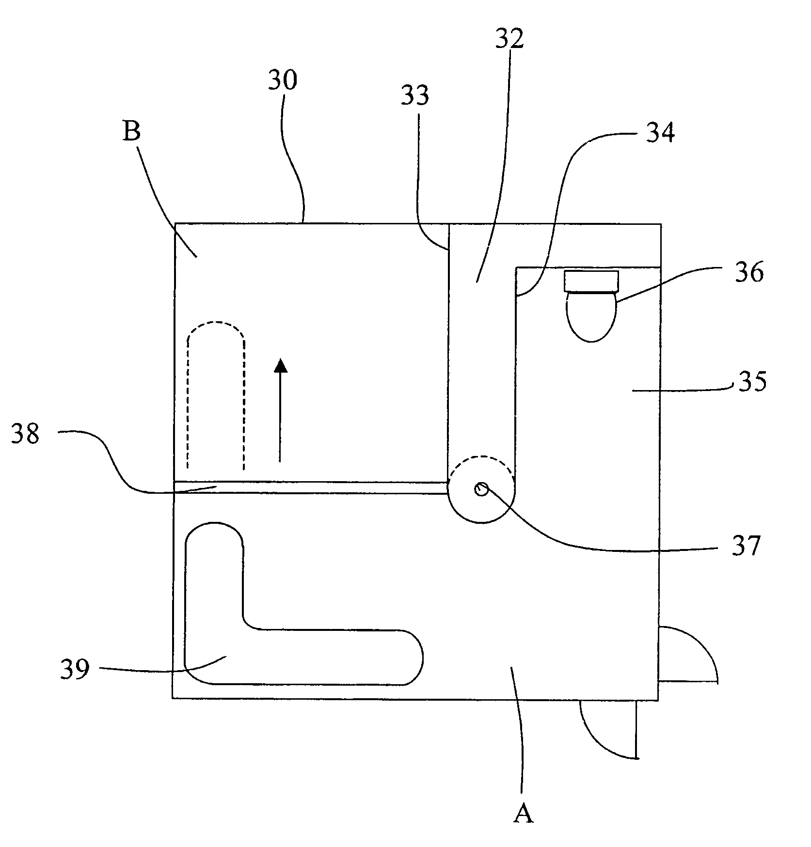
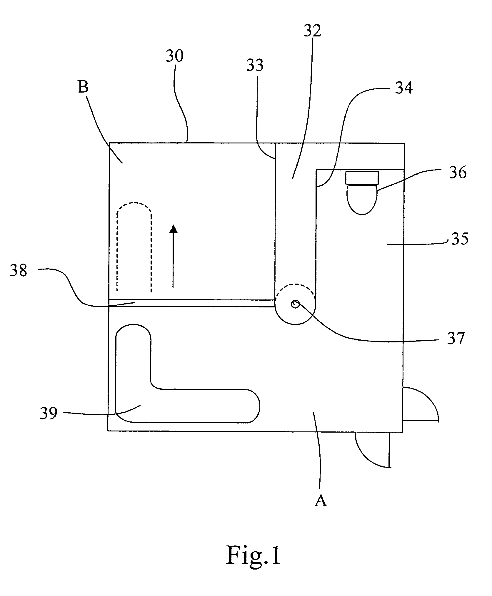
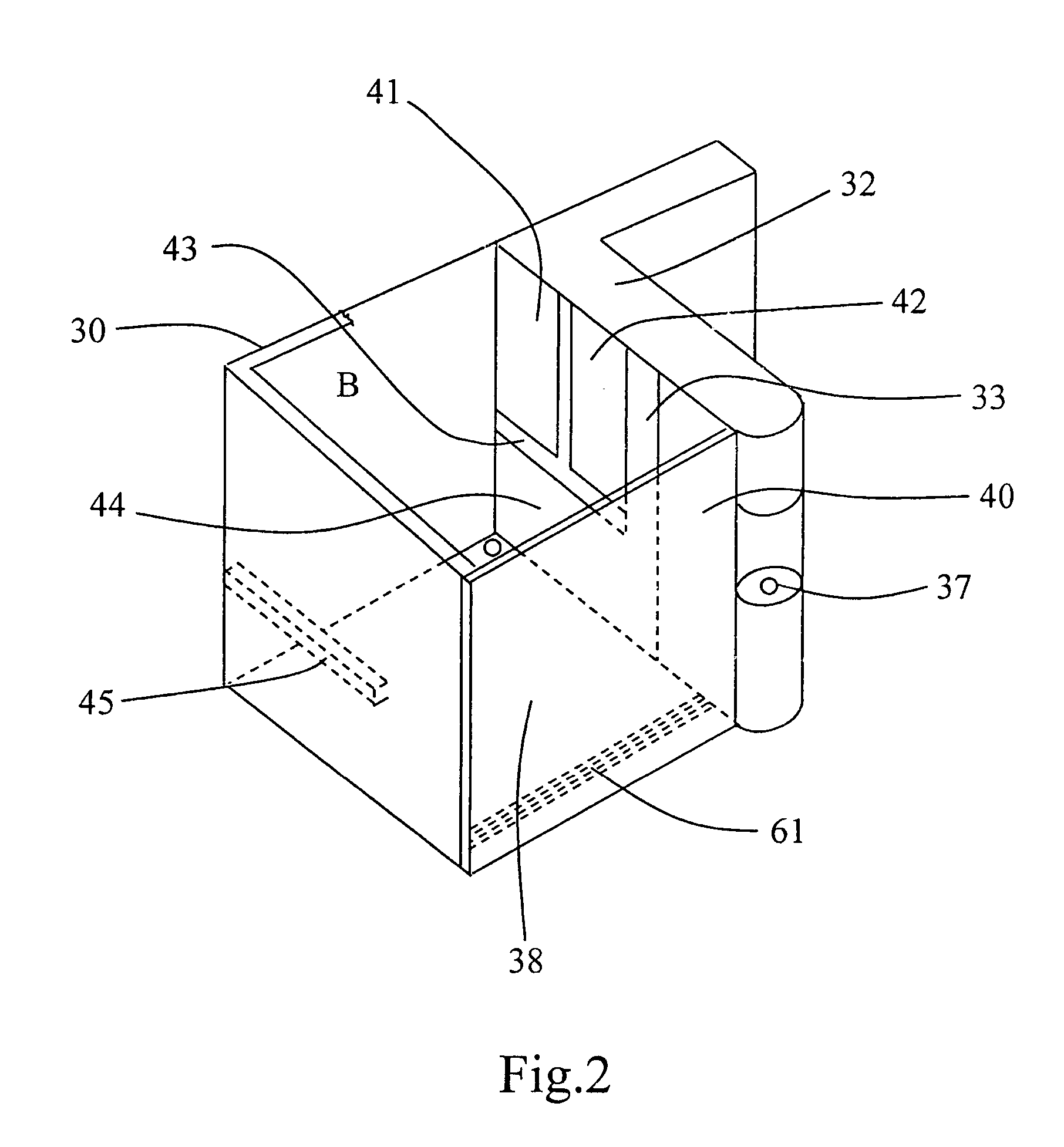
[0048]As emerges at first glance from FIG. 1, this embodiment differs essentially from the first embodiment in the square shape of the facility 30 and in that the wet room B occupies only a portion of the sides of the square. In addition, the sliding door, the oblique partition and the triangular space of the first embodiment are advantageously combined into an L-shaped technical space 32 (technical center C.T and storage room), the leg of the L being formed by two parallel walls 33 and 34, the wall 33 limiting the wet room, while the wall 34 delimits a rectangular space 35 in which a WC 36 is placed. A washbasin 37 is advantageously situated at the inner end of the technical space 32. There is a movable partition 38 that can be moved in the direction of the arrow. In front of the washbasin 37, the dry dressing room A is laid out in which is disposed a rest bed 39 mounted on rollers and articulated. The ...


PUM


Abstract

The invention concerns a rectangular, in particular square, multipurpose sanitary installation, comprising essentially two separate units, namely a dry toilet unit (A) including essentially a wash basin and a toilet and a rectangular washroom (B). the washroom is delimited by at least two adjacent walls of the installation and by a mobile element perpendicular to one side of the installation and moveable parallel to itself, such that the surface of the washroom (B) may vary and with it the surface of the dry toilet unit (A). A mobile element may be used as water-retaining wall or as bench.

Description

CROSS REFERENCE TO RELATED APPLICATIONS[0001]This application is a Continuation of PCT Application No. PCT / IB2003 / 004654 filed Oct. 16, 2003, claiming priority of French Application No. 02 / 12917 filed Oct. 17, 2002, which is included in its entirety by reference made hereto.BACKGROUND OF THE INVENTION[0002]1. Field of the Invention[0003]The subject of the present invention is a rectangular, particularly square multipurpose sanitary facility, comprising essentially two distinct spaces, that is a space for the dry dressing room comprising essentially a washbasin and a WC and a rectangular wet room.[0004]2. Description of the Related Art[0005]From patent FR 1 379 768 a domestic hygiene assembly is known consisting of three distinct enclosures forming respectively a dressing room comprising a washbasin, a wet room comprising a tub-bath and a dressing room comprising a WC, these enclosures being able to be grouped together as desired to form a coherent set in which the wet room is entire...

Claims


Application Information

Patent Timeline
Patent Type & Authority Patents(United States)
IPC IPC(8): A47K4/00E03C1/01
CPCA47K4/00Y02A50/30
Inventor HABEGGER, VIRGILE
Owner HABEGGER VIRGILE
Why Eureka
Try Eureka