Method of operating auger icemaking machine

a technology of icemaking machine and auger, which is applied in the direction of ice production, lighting and heating apparatus, domestic applications, etc., can solve the problems of failure of full-state detection, impeding the discharge of compressed ice, and limited difference between high level and low level detected by stored ice detection means

Inactive Publication Date: 2006-06-20
HOSHIZAKI ELECTRIC CO LTD
View PDF17 Cites 27 Cited by
  • Summary
  • Abstract
  • Description
  • Claims
  • Application Information

AI Technical Summary

Problems solved by technology

However, the differential between the high level and low level detected by the stored-ice detection means is limited to a small value, and after detection of the high level (i.e., the stop of the ice-making operation), the low level resulting from slight melting of the compressed ice or from a small quantity of discharge thereof is detected prior to the restart of the ice-making operation.
Since such scrap ice is very soft, it sticks to the inner wall surface of the stocker in the form of a donut, then changing into a block of ice, thus impeding the discharge of compressed ice.
In addition, a full-state detection failure could result if the block of ice grows to a level at which the stored-ice detection means is disposed.
Therefore, if ice-making operation is continued in that state or the machine remains exposed to a cryogenic atmosphere, the entire stocker encounters the serious trouble of freezing.
Furthermore, not only the compressed ice could not only become a mass too large to be discharged from the stocker, but also is indicated the likelihood of damage being caused to the auger motor and other ice-making mechanical sections by significant loading.
Therefore, the quantity of compressed ice is likely to have significantly decreased by the time the block of ice melts and collapses to cause the stored-ice detection means to detect a low level.
Consequently, a shortage of ice could occur since the stocker will have become empty by the time a subsequent delay time elapses.
In addition, although the stocker of the foregoing ice-making machine is heat-insulated, melting of the compressed ice in the stocker with time reduces the storage level, and even if the compressed ice is not discharged, the low level may be detected.
Conversely, it is indicated the problem that if the above-mentioned delay time is set to take a large value fit for the time of the year when ice slowly melts, such as in the winter, the stocker runs out of compressed ice at the time of the year when ice melts rapidly, as in the summer.
In this case, however, the number of stored-ice detection means increases, thereby increasing costs, disadvantageously.

Method used


Image

  • Method of operating auger icemaking machine
  • Method of operating auger icemaking machine
  • Method of operating auger icemaking machine

Examples


first embodiment

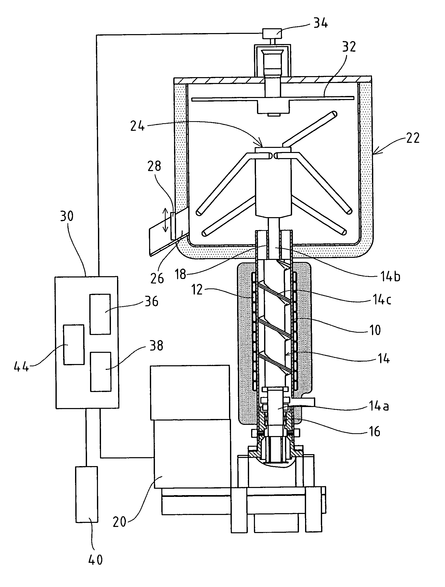
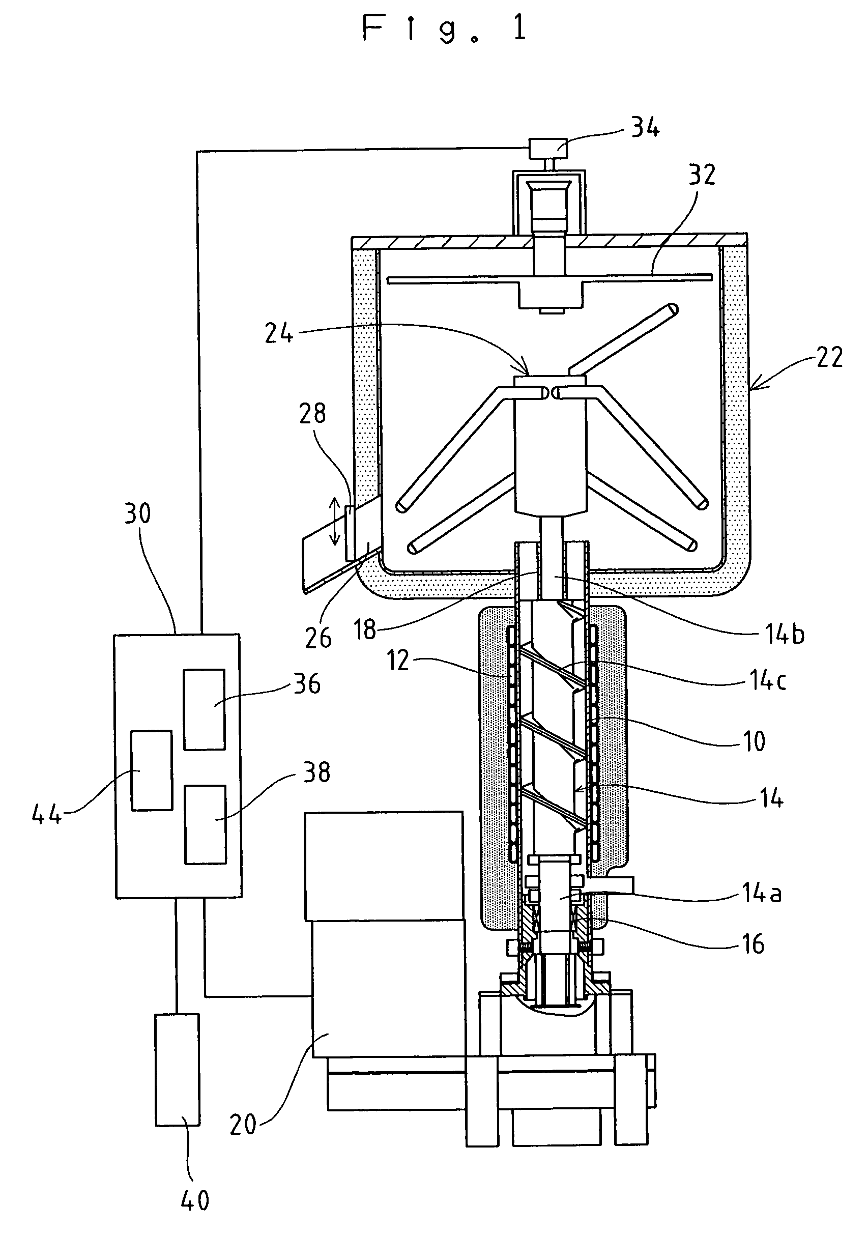
[0020]FIG. 1 shows a schematic configuration of an auger ice-making machine to which is applied an operating method according to the present invention. In FIG. 1, the auger ice-making machine has, on an outer surface of a cylindrical refrigeration casing 10, an evaporation pipe (evaporation section) 12 communicating with a refrigerating system is tightly wound, and the machine is adapted to forcibly cool the refrigeration casing 10 by circulating a refrigerant through the evaporation pipe 12 when ice-making operation is started. In addition, the refrigeration casing 10 is adapted so that when ice-making water is supplied from an ice-making water tank (not shown) at a required level and ice-making operation is started, the refrigeration casing 10 is forcibly cooled. Hence, the ice-making water starts freezing gradually from an inner wall surface of the casing, and thus thin ice of a laminar form is formed.

[0021]Inside the refrigeration casing 10, an auger screw 14 is inserted, a lowe...

third embodiment

[0060]The controller 30 in the auger ice-making machine has a temperature sensor 42 connected for detecting an ambient temperature, a temperature Q detected by the sensor 42 being input to the controller 30. The controller 30 is adapted to calculate a unit quantity of molten ice (per unit time), FA, from the detected temperature Q.

[0061]That is, the applicant has experimentally found that as shown in FIG. 7, the unit quantity of molten ice, FA, of the compressed ice in the stocker 22 is proportional to an ambient temperature. The applicant has also verified that the unit quantity of molten ice, FA, at the ambient temperature can be calculated from the product of the constant N (4.47) obtained from the approximated line of FIG. 5, and the detected temperature Q.

[0062]In the operating method of the third embodiment, when the stored-ice detector 34 detects high level H, the controller 30 calculates the unit quantity of molten ice, FA, that is the quantity of melting of compressed ice ...


PUM


Abstract

A method of operating an auger ice-making machine having a refrigeration casing, an auger screw rotatably disposed inside the casing and feeding, while scraping, the ice frozen on an inner wall surface of the casing, a stocker for storing / retaining the ice fed, the stocker being formed with an ice discharge port of the stocker in order to discharge the ice to an exterior of the machine by being opened, and a stored-ice detector for detecting a high level, and a low level, of a quantity of ice stored within the stocker, wherein: when the stored-ice detector detects the high level, a controller is activated to stop ice-making operation, and when the quantity of ice stored decreases below the low level by a required quantity, the controller restarts the ice-making operation; and when the controller judges, during a stopped state of the ice-making operation, that a block of ice has occurred in the stocker, the controller restarts the ice-making operation, provided that the stored-ice detector has detected the low level.

Description

BACKGROUND OF THE INVENTION[0001]1. Field of the Invention[0002]This invention relates to a method of operating an auger ice-making machine, and more particularly, to a method of operating an auger ice-making machine which feeds by means of an auger screw, while scraping, the ice frozen on an inner wall surface of a refrigeration casing, compresses the frozen ice by means of a push head, and stores in a stocker the compressed ice obtained.[0003]2. Description of the Related Art[0004]In the kitchens of coffee shops, restaurants, and the like, ice-making machines for manufacturing blocks of ice of required shapes have been conveniently used for a long time, and these types of machines include an auger type of ice-making machine used for continuously manufacturing blocks of ice in the form of small pieces such as ice chips or ice flakes. In the auger ice-making machine, when ice-making operation is started with ice-making water stored within a cylindrical refrigeration casing at a requ...

Claims


Application Information

Patent Timeline
Patent Type & Authority Patents(United States)
IPC IPC(8): F25C1/14F25C5/18
CPCF25C1/147F25C5/187F25C2600/04F25C5/142
Inventor TSUCHIKAWA, KOJIHIBINO, TAKASHIIKARI, HIDEYUKI
Owner HOSHIZAKI ELECTRIC CO LTD
Why Eureka
Try Eureka