Thermally-assisted perpendicular magnetic recording system and head

a magnetic recording and perpendicular magnetic technology, applied in the field of thermally assisted magnetic recording (tamr) system, can solve the problems of data loss, adjacent-track interference (ati), and the inability to exceed the write field capability of the recording head

Inactive Publication Date: 2006-06-27
HITACHI GLOBAL STORAGE TECH NETHERLANDS BV
View PDF13 Cites 60 Cited by
  • Summary
  • Abstract
  • Description
  • Claims
  • Application Information

AI Technical Summary

Benefits of technology

[0014]For a fuller understanding of the nature and advantages of the present invention, reference should be made to the following detailed description taken together with the accompanying figures.

Problems solved by technology

Obviously, H0 cannot exceed the write field capability of the recording head, which currently is limited to about 9 kOe for longitudinal recording, and perhaps 15 kOe for perpendicular recording.
One problem with a wide-area heater is adjacent-track interference (ATI).
Also, even in the absence of a magnetic field, the thermal decay rate in adjacent tracks is accelerated over that at ambient temperature and thus data loss may occur.
A disadvantage of the small-area resistive heater is that due to the relatively inefficient heat transfer the heater temperatures required to reach a desired media temperature are very high.
Ultimately, however, perpendicular magnetic recording is also limited by the superparamagnetic effect.

Method used


Image

  • Thermally-assisted perpendicular magnetic recording system and head
  • Thermally-assisted perpendicular magnetic recording system and head
  • Thermally-assisted perpendicular magnetic recording system and head

Examples


Embodiment Construction

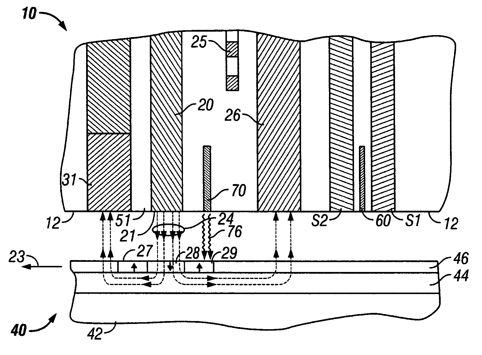
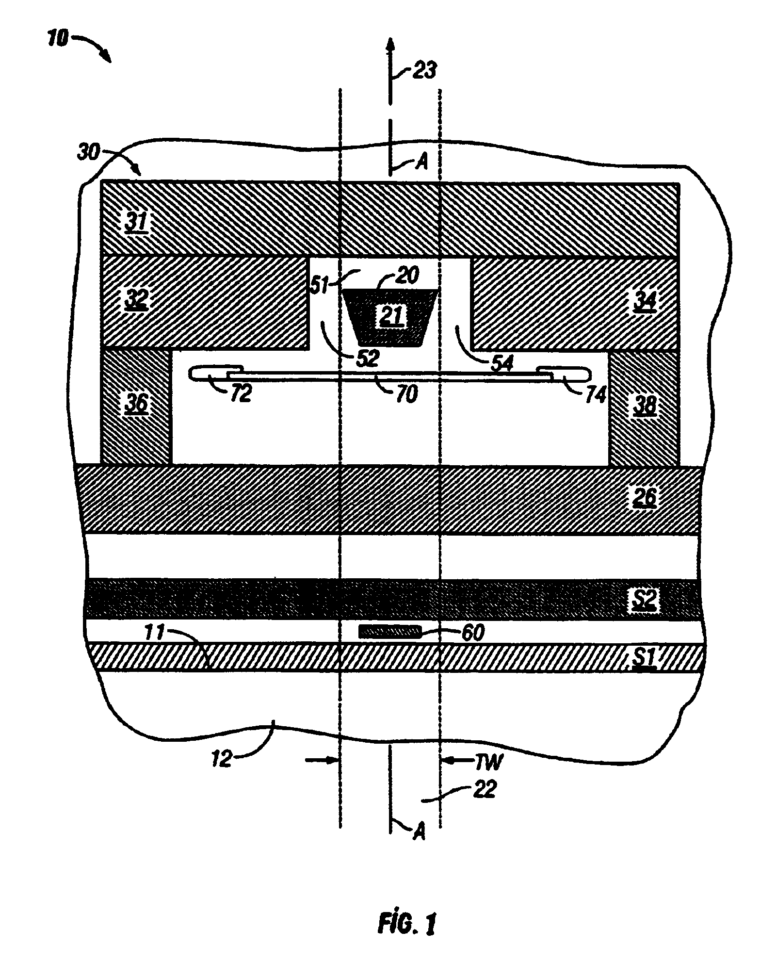
[0018]FIG. 1 is an illustration of the recording head 10 of the present invention as seen from the recording medium. The head 10 includes a series of thin films and structures formed on the trailing surface 11 of a head carrier. The head carrier has a recording-layer-facing surface 12 oriented generally perpendicular to trailing surface 11. In a disk drive embodiment the head carrier is an air-bearing slider, surface 11 is the end of the slider on which the thin films are formed, and surface 12 is the ABS of the slider. The ABS 12 is the recording-layer-facing surface of the slider that faces the disk and is shown without the thin protective overcoat typically present in an actual slider. The recording-layer-facing surface shall mean the surface of the head carrier that is covered with a thin protective overcoat, the actual outer surface of the head carrier if there is no overcoat, or the outer surface of the overcoat. The phrase “substantially at the recording-layer-facing surface”...


PUM

PropertyMeasurementUnit
widthaaaaaaaaaa
widthaaaaaaaaaa
widthaaaaaaaaaa

Abstract

A thermally-assisted perpendicular magnetic recording head includes a write pole tip for generating a magnetic write field in the perpendicular magnetic recording layer, a magnetic shield that confines the write field essentially to the data track to be recorded, an electrically resistive heater for heating the recording layer in the presence of the write field, and a return pole. The write pole tip width essentially defines data track width and is substantially surrounded by the magnetic shield. The shield may include side shields with ends located on opposite sides of the write pole tip and a trailing shield having an end spaced from the write pole tip. The resistive heater is wider than the data track and heats both the data track and adjacent tracks, but thermally-assisted magnetic recording occurs only in the data track because the confined magnetic field in the adjacent tracks is less than the required write field.

Description

TECHNICAL FIELD[0001]This invention relates generally to a thermally-assisted magnetic recording (TAMR) system, in which data are written while the magnetic recording layer is at an elevated temperature, and more specifically to a TAMR system for perpendicular recording and a TAMR head with an electrically resistive heater.BACKGROUND OF THE INVENTION[0002]Magnetic recording hard disk drives use a thin-film inductive write head supported on the end of a rotary actuator arm to record data in the recording layer of a rotating disk. The write head is patterned on the trailing surface of a head carrier, such as a slider with an air-bearing surface (ABS) that allows the slider to ride on a thin film of air above the surface of the rotating disk. The write head is an inductive head with a thin film electrical coil located between the poles of a magnetic yoke. When write current is applied to the coil, the pole tips provide a localized magnetic field across a gap that magnetizes regions of ...

Claims


Application Information

Patent Timeline
Patent Type & Authority Patents(United States)
IPC IPC(8): G11B5/02G11B5/00G11B5/012G11B5/11G11B5/127G11B5/31G11B5/39G11B11/00
CPCG11B5/012G11B5/11G11B5/127G11B5/1278G11B5/315G11B5/3967G11B2005/0002G11B2005/0005G11B2005/0021G11B5/3143G11B5/314
Inventor TERRIS, BRUCE DAVIDTHIELE, JAN-ULRICH
Owner HITACHI GLOBAL STORAGE TECH NETHERLANDS BV
Why Eureka
Try Eureka