
Laser power sensor for thermally assisted magnetic recording

a technology of power sensor, which is applied in the field of laser power sensor for thermally assisted magnetic recording, can solve the problems of inherently limited grain miniaturization, corrupted data stored on the disk, and limited ksub>u /sub>,

Active Publication Date: 2009-09-10
WESTERN DIGITAL TECH INC
View PDF25 Cites 56 Cited by
  • Summary
  • Abstract
  • Description
  • Claims
  • Application Information

AI Technical Summary

Benefits of technology

The present invention provides an apparatus, systems, and methods for monitoring laser light output in thermally assisted magnetic recording disk drives. The invention addresses the problem of unsolved needs in the art and provides a solution for monitoring the power level of the laser in real-time during the recording process. The invention includes a rotational magnetic medium, an actuator arm, and a slider secured to the actuator arm. The read / write head is secured to the slider and the laser delivers laser light to a small spot on the rotational magnetic medium. The invention also includes a measurement module, a determination module, and an interface module for measuring and reporting the power level of the laser light. The invention provides a solution for improving the accuracy and efficiency of thermally assisted magnetic recording disk drives.

Problems solved by technology

The ability of individual magnetic grains to be magnetized in one direction or the other, however, poses problems where grains are extremely small.
Where this occurs, data stored on the disk is corrupted.
Thus, while it is desirable to make smaller grains to support higher density recording with less noise, grain miniaturization is inherently limited by the superparamagnetic effect.
However, the increase in Ku is limited by the point where coercivity Hc becomes too great for the media to be written by conventional write heads.
However, TAR technology does not utilize currently available commercial lasers with photodiodes because of the added bulk associated with the commercial laser and photodiode.
Alternatives to current commercial photodiodes such as a custom photodiode are unpromising because of the added costs and complexity associated with adding another element to the read / write head.

Method used


Image

  • Laser power sensor for thermally assisted magnetic recording
  • Laser power sensor for thermally assisted magnetic recording
  • Laser power sensor for thermally assisted magnetic recording

Examples


Embodiment Construction

[0044]Reference throughout this specification to “one embodiment,”“an embodiment,” or similar language means that a particular feature, structure, or characteristic described in connection with the embodiment is included in at least one embodiment of the present invention. Thus, appearances of the phrases “in one embodiment,”“in an embodiment,” and similar language throughout this specification may, but do not necessarily, all refer to the same embodiment.

[0045]Furthermore, the described features, advantages, and characteristics of the invention may be combined in any suitable manner in one or more embodiments. One skilled in the relevant art will recognize that the invention can be practiced without one or more of the specific features or advantages of a particular embodiment. In other instances, additional features and advantages may be recognized in certain embodiments that may not be present in all embodiments of the invention.

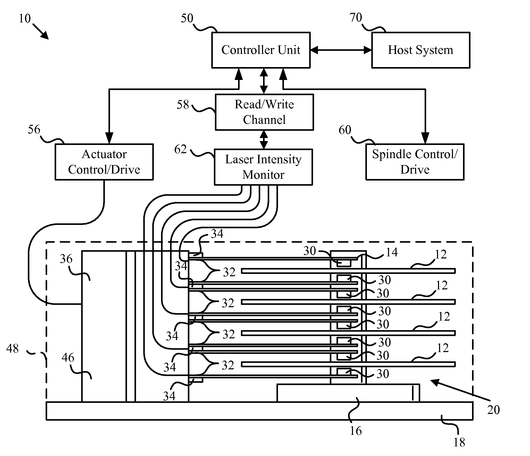
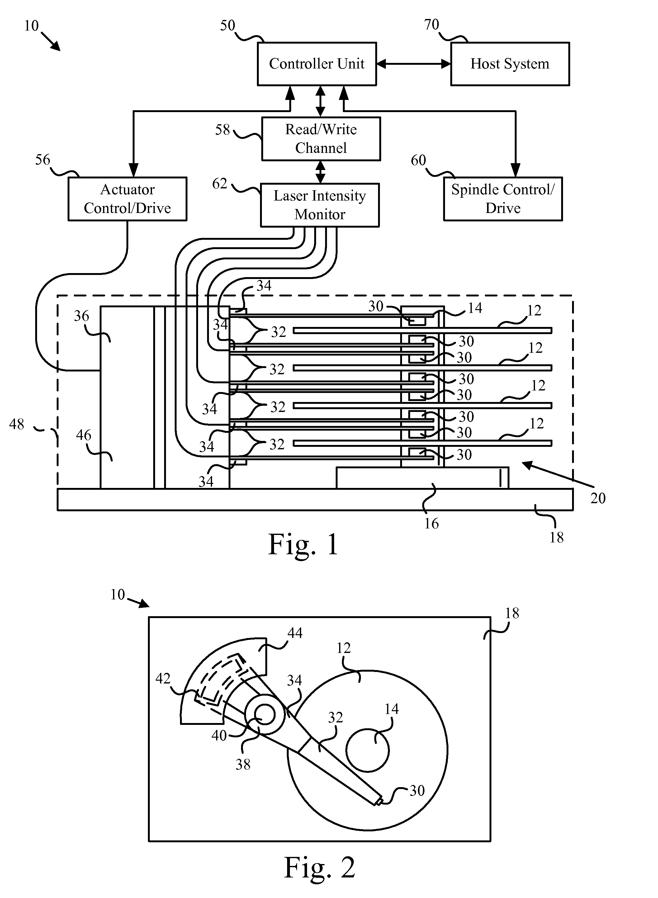
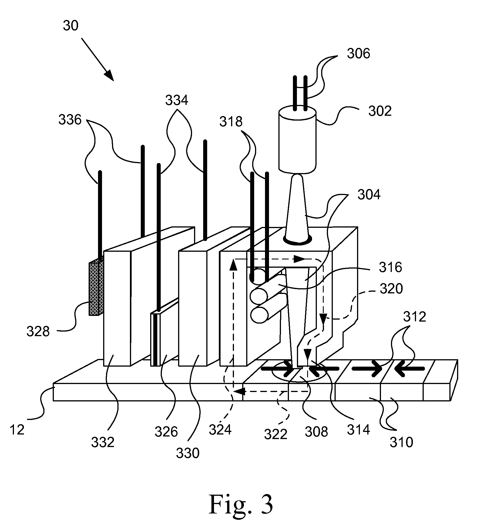
[0046]FIGS. 1 and 2 show schematic diagrams of one e...


PUM

PropertyMeasurementUnit
diameteraaaaaaaaaa
diameteraaaaaaaaaa
diameteraaaaaaaaaa

Abstract

An apparatus, system, and method for measuring thermally induced electric resistance changes in thermally assisted magnetic recording are disclosed for monitoring laser light output in thermally assisted magnetic recording disk drives. An electrical lead is coupled to a read / write head element. A first electrical resistance in the read / write head element is measured. The read / write head is heated by a laser and a second electrical resistance in the read / write head element is measured. The electrical resistance may be monitored at regular intervals when the read / write head element is on the ramp or the electrical resistance measurements may be continuously monitored as the read / write head flies over the magnetic media.

Description

BACKGROUND OF THE INVENTION[0001]1. Field of the Invention[0002]This invention relates to apparatus, systems, and methods for monitoring laser light output in thermally assisted magnetic recording disk drives.[0003]2. Description of the Related Art[0004]Hard-disk drives provide data storage for data processing systems in computers and servers, and are becoming increasingly pervasive in media players, digital recorders, and other personal devices. Advances in hard-disk drive technology have made it possible for a user to store an immense amount of digital information on an increasingly small disk, and to selectively retrieve and alter portions of such information almost instantaneously. Particularly, recent developments have simplified hard-disk drive manufacture while yielding increased track densities, thus promoting increased data storage capabilities at reduced costs.[0005]A typical hard-disk drive will include a stack of disks or “platters” mounted on a common spindle. The surfa...

Claims


Application Information

Patent Timeline
Patent Type & Authority Applications(United States)
IPC IPC(8): G11B13/04G11B5/00G11B13/00
CPCG11B5/314G11B5/40G11B2005/0021G11B5/6064G11B2005/0005G11B5/455G11B5/607
Inventor JUANG, JIA-YANGREILEY, TIMOTHY C.STRAND, TIMOTHY C.
Owner WESTERN DIGITAL TECH INC
Learn More