Light source unit for thermally-assisted magnetic recording capable of monitoring of light output

a technology of thermally assisted magnetic recording and light output, which is applied in the direction of optical radiation measurement, instruments, mounting heads within the housing, etc., can solve the problems of difficult installation of monitoring systems, difficult to monitor the magnetic recording medium, and degradation of the thermal stability of the magnetization, so as to achieve low loss of light from the light source, high efficiency, and high efficiency

Active Publication Date: 2011-09-22
TDK CORPARATION +1
View PDF9 Cites 55 Cited by
  • Summary
  • Abstract
  • Description
  • Claims
  • Application Information

AI Technical Summary

Benefits of technology

[0017]The light-source unit according to the present invention is provided with a photodetector which enables constant monitoring of light output from the light source. Here, the light-receiving surface of the photodetector and the rear light-emission center of the light source can be sufficiently close to each other; thus, the light output from the rear light-emission center of the light source can be monitored with high efficiency. Accordingly, feedback adjustment of light output from the light source that emits light for thermal assist can be accomplished. This adjustment enables light output from the light source to be controlled in response to changes in light output due to surroundings and to changes with time to stabilize the intensity of light with which a magnetic recording medium is irradiated for thermal assist. Consequently, a region of a magnetic recording medium where data is to be written can be properly and stably heated. Therefore, a good thermally-assisted magnetic recording can be accomplished.
[0023]In the thermally-assisted magnetic recording head according to the present invention, it is preferable that a light-receiving center in a light-receiving surface of the photodetector, the rear light-emission center of the light source, the light-emission center of the light source, and a light-receiving center in a light-receiving surface of the optical system are located substantially in a straight line, and a near-field light generator (NFL-generator) that emits a NF-light for thermal assist from an end extending to a head end surface on an opposed-to-medium surface side is provided in or near the straight line. Since a series of these optical components are disposed substantially in line in the head, a highly efficient configuration is achieved in which loss in light from the light source is minimized. That is, NF-light for thermal assist that is generated from the NFL-generator and has a sufficient intensity, and monitor output from the photodetector that has a required intensity, can be obtained with a high efficiency. In this case, a distance between a surface of the photodetector that is on the side opposite to the light-receiving surface and the end of the NFL-generator extending to the head end surface on the opposed-to-medium surface side is preferably less than or equal to 700 μm (micrometers). This setting of the distance can improve the flying stability of the head and reduce the thickness of the head gimbal assembly (HGA) containing the head.
[0035]depositing a conductive material on the joining surfaces of the plurality of stacked light-source-unit row bars to form an adhesion material layer for bonding with a slider while using the bank layer to prevent the conductive material from being deposited at least between the first and second lead electrode layers.

Problems solved by technology

However, the decrease in size of the magnetic grains raises a problem of degradation in thermal stability of the magnetization due to the decrease in volume.
As a result, the head cannot write data to the magnetic recording medium when the anisotropic magnetic field of the medium exceeds the write field limit.
However, it is difficult to install a system for monitoring the light in an element-integration surface of a head for thermal assist together with an optical system that propagates the light for thermal assist, because of a limited area of the element-integration surface.
In these circumstances, little has been done to monitor light output from the light source for thermal assist.

Method used


Image

  • Light source unit for thermally-assisted magnetic recording capable of monitoring of light output
  • Light source unit for thermally-assisted magnetic recording capable of monitoring of light output
  • Light source unit for thermally-assisted magnetic recording capable of monitoring of light output

Examples


Embodiment Construction

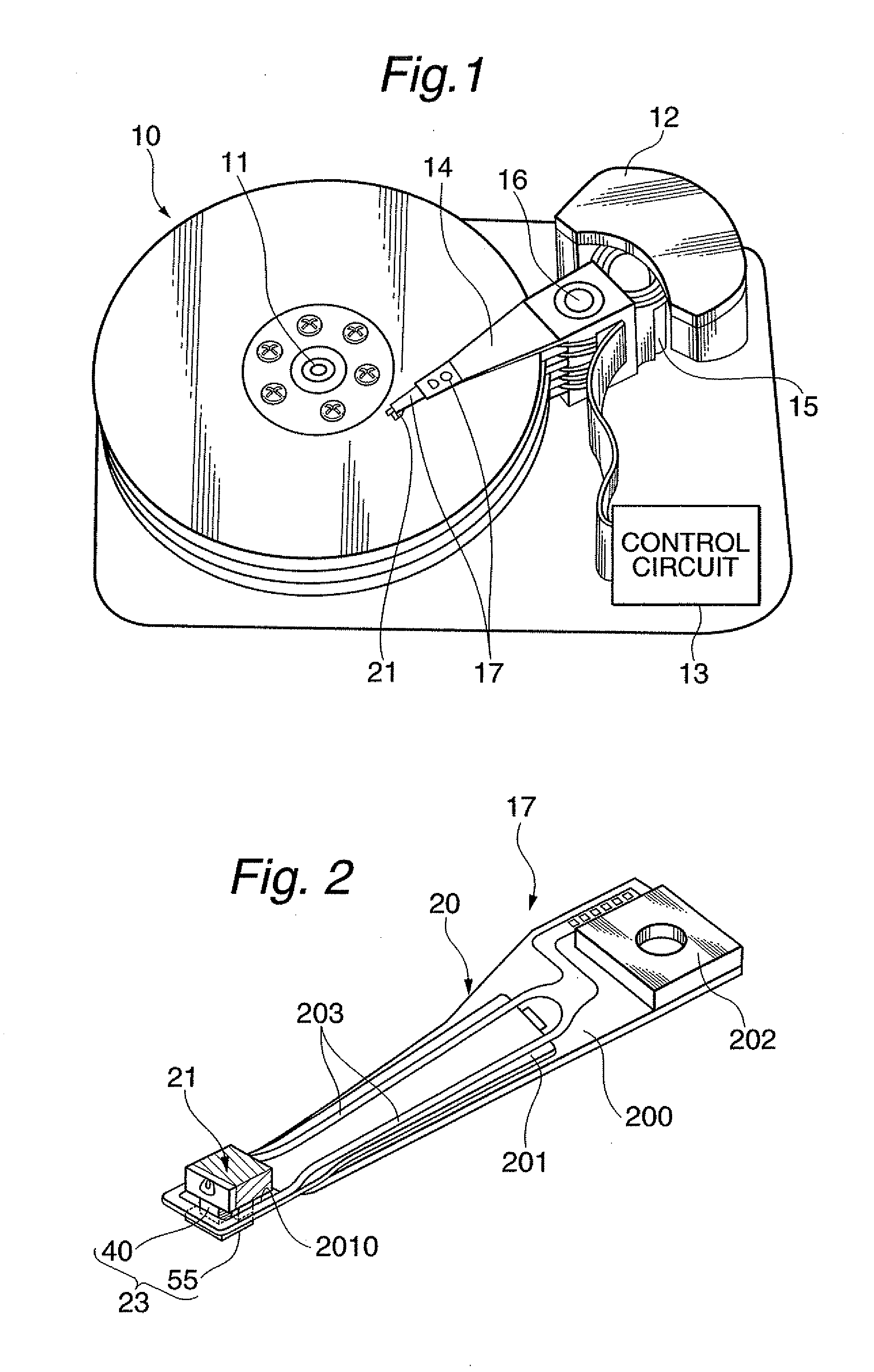
[0049]FIG. 1 shows a perspective view schematically illustrating a structure of a major part in one embodiment of a magnetic disk apparatus according to the present invention.

[0050]A magnetic disk apparatus as a magnetic recording apparatus shown in FIG. 1 includes: a plurality of magnetic disks 10 rotating around a rotational axis of a spindle motor 11; an assembly carriage device 12 provided with a plurality of drive arms 14 thereon; an HGA 17 attached on the top end portion of each drive arm 14 and provided with a thermally-assisted magnetic recording head 21; and a recording / reproducing and light-emission control circuit 13 for controlling write / read operations of the thermally-assisted magnetic recording head 21 and further for controlling the emission operation of a laser diode as a light source that generates laser light for thermally-assisted magnetic recording, based on monitoring output generated from a light detector for monitoring the output of the light source, which wi...


PUM

PropertyMeasurementUnit
temperaturesaaaaaaaaaa
width WSCaaaaaaaaaa
thickness TSCaaaaaaaaaa

Abstract

Provided is a light source unit that is to be joined to a slider to form a thermally-assisted magnetic recording head. The light source unit comprises: a unit substrate having a source-installation surface; a light source provided in the source-installation surface and emitting thermal-assist light; and a photodetector bonded to a rear joining surface of the unit substrate in such a manner that a rear light-emission center of the light source is covered with a light-receiving surface of the photodetector. The photodetector can be sufficiently close to the light source; thus, constant feedback adjustment with high efficiency for the light output of the light source can be performed. This adjustment enables light output from the light source to be controlled in response to changes in light output due to surroundings and to changes with time to stabilize the intensity of light with which a magnetic recording medium is irradiated.

Description

BACKGROUND OF THE INVENTION[0001]1. Field of the Invention[0002]The present invention relates to a light source unit including a light source for emitting light used for thermally-assisted magnetic recording, and to a thermally-assisted magnetic recording head constituted by joining the light source unit and a slider. The present invention further relates to a method for manufacturing the light source unit.[0003]2. Description of the Related Art[0004]As the recording densities of magnetic recording apparatuses become higher, as represented by magnetic disk apparatuses, further improvement has been required in the performance of thin-film magnetic heads and magnetic recording media. The magnetic recording medium is generally a kind of discontinuous body of magnetic grains gathered together, and each of the magnetic grains has a single magnetic domain structure. Here, one record bit consists of a plurality of the magnetic grains. Therefore, in order to improve the recording density, i...

Claims


Application Information

Patent Timeline
Patent Type & Authority Applications(United States)
IPC IPC(8): G11B11/00G01J1/32B32B38/00
CPCG11B5/105Y10T156/1052G11B2005/0021G11B5/314G11B5/6088
Inventor SHIMAZAWA, KOJITSUCHIYA, YOSHIHIROTAKAYAMA, SEIICHIMORI, NOBUYUKIITO, YASUHIROTANAKA, KOSUKESHINDO, OSAMUFUJII, RYUJIHONDA, TAKASHISASAKI, YOSHITAKA
Owner TDK CORPARATION
Why Eureka
Try Eureka