Movable jaw type holding device

a technology of holding device and jaw, which is applied in the field of hand tools, can solve the problems of accidental force away from the pin e, damage or deformation of the spring c, and the design of the holding device of the type of pliers is still not satisfactory in function, and achieves the effect of stable and durable us

Inactive Publication Date: 2006-07-04
HWANG CHERNG BIN
View PDF10 Cites 9 Cited by
  • Summary
  • Abstract
  • Description
  • Claims
  • Application Information

AI Technical Summary

Benefits of technology

[0007]The present invention has been accomplished under the circumstances in view. It is the main object of the present invention to provide a movable jaw type holding device, which is stable and durable in use. It is another object of the present invention to provide a movable jaw type holding device, which eliminates deposition of dust to the gaps in between the parts.

Problems solved by technology

Because the spring C is provided at an outer side relative to the movable jaw B, it is exposed to the outside and tends to be damaged or deformed by an impact accidentally.
Further, because no fastening means is provided to secure the spring C to the pin E firmly, the spring C tends to be forced away from the pin E accidentally.
This design of fish holding device of the pliers type is still not satisfactory in function.
One drawback of this design of fish holding device of the pliers type is that the space in between the jaw members 10 and 12 around the spring 54 tends to be covered with dust.
Another drawback of this design of fish holding device of the pliers type is that the limited contact area between the thin pads 36 and 38 of the handle portions 10 and 12 is insufficient to support the jaw members 10 and 12 stably in balance, and the jaw members 10 and 12 will start to vibrate after long use of the device.
Still another drawback of this design of fish holding device of the pliers type is that the pivot 14 (screw bolt 42 and nut 48) pivotally securing the two identical handle and the jaw members 10 and 12 together wears quickly with use, resulting in vibration of the jaw members 10 and 12.

Method used


Image

  • Movable jaw type holding device
  • Movable jaw type holding device
  • Movable jaw type holding device

Examples


Embodiment Construction

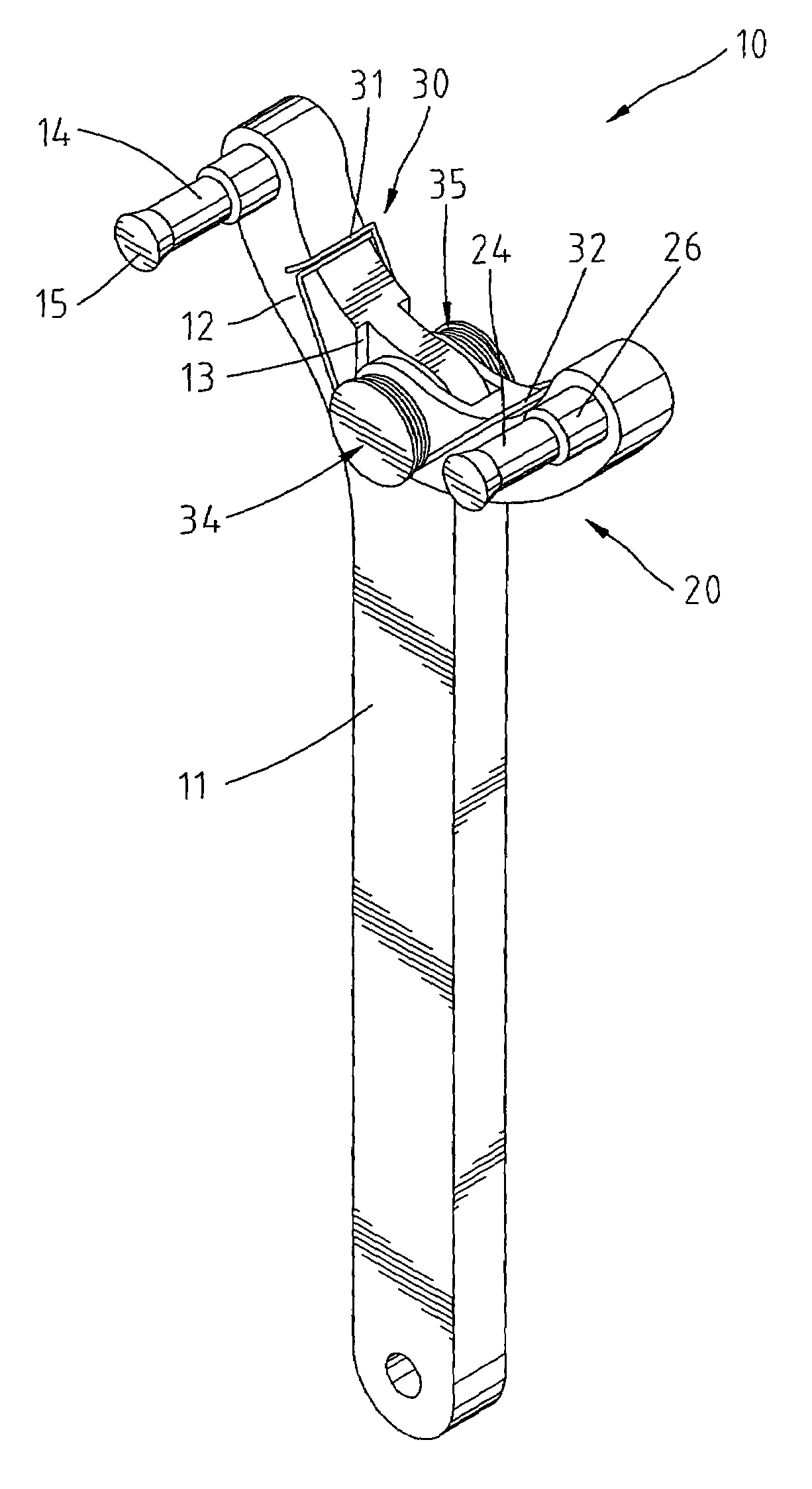
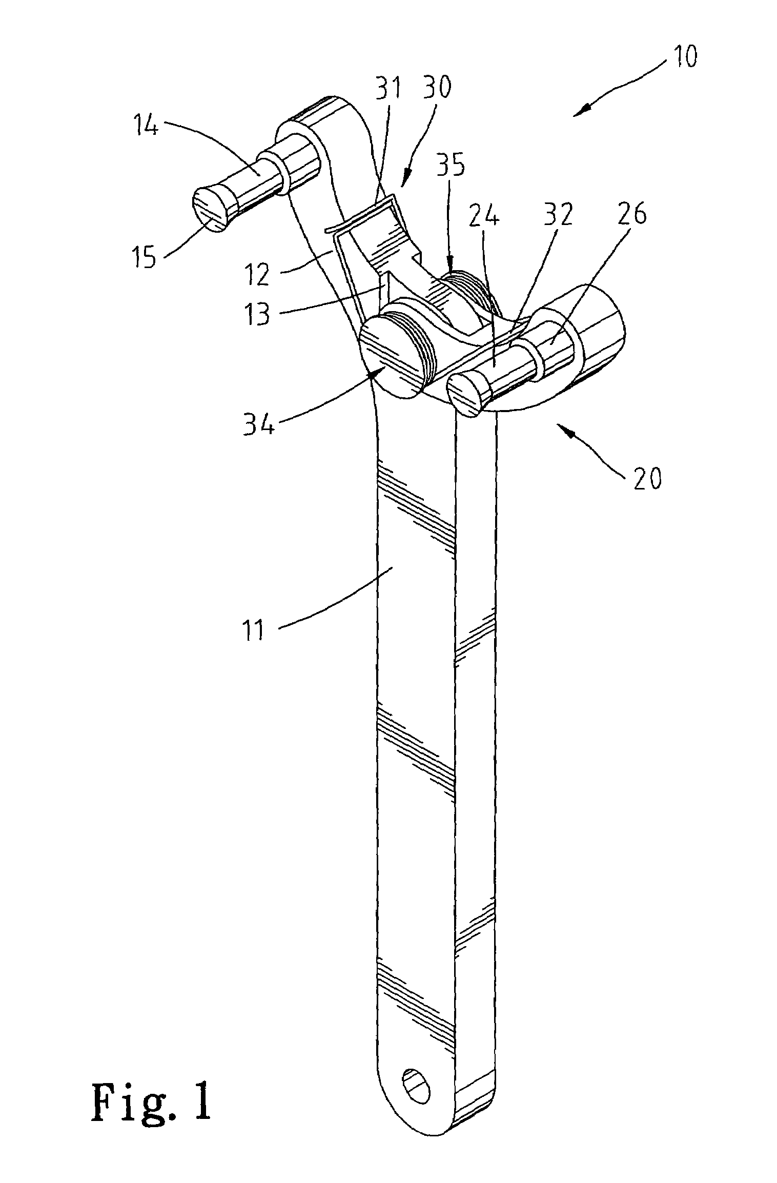
[0016]Referring to FIG. 1, a movable jaw type holding device 10 in accordance with the present invention is shown including a handle 11, a movable jaw member 20, and a spring member 30. The handle 11 has one end terminating in a fixed jaw member 12. A pivot 34 pivots the movable jaw member 20 to the handle 11 adjacent to the fixed jaw member 12. The spring member 30 is mounted on the pivot 34, having two distal ends 31 and 32 respectively stopped against the fixed jaw member 12 and the movable jaw member 20. Further, first and second rod members 14 and 24 are respectively affixed to the fixed jaw member 12 and the movable jaw member 20 for holding or turning things.

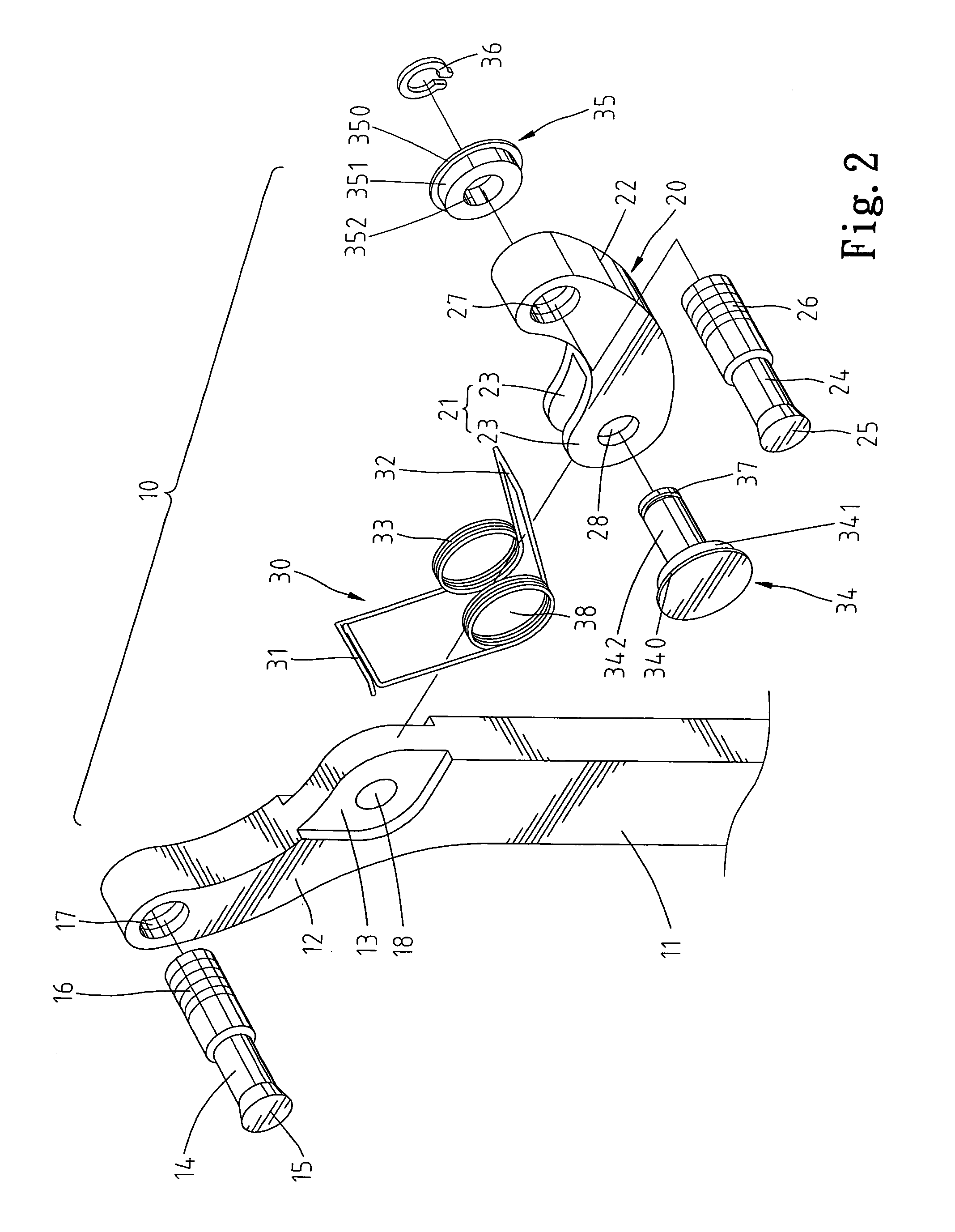
[0017]Referring to FIGS. 2 and 3 and FIG. 1 again, the fixed jaw member 12 has a screw hole 17 transversely disposed at the distal one end thereof for holding the first rod member 14. The first rod member 14 has a tapered head 15 at one end, and a screw rod 16 at the other end for threading into the screw hole 17 of the f...


PUM


Abstract

A movable jaw holding device includes a handle having a fixed jaw member holding a first rod member. A movable jaw member is pivoted to the handle by a pivot and holds a second rod member. A C-shaped retainer fastened to the shank of the pivot secures to secures the pivot to the handle and the movable jaw member. A spring member mounted on the pivot and stopped between the fixed jaw member and the movable jaw member is well protected by the head of the pivot and a cushion ring at one end of the pivot.

Description

CROSS-REFERENCE[0001]The present application is a continuation-in-part application of U.S. patent application Ser. No. 10 / 385,943, filed Mar. 10, 2003, now abandoned.BACKGROUND OF THE INVENTION[0002]1. Field of the Invention[0003]The present invention relates to a hand tool and, more particularly, to a movable jaw type holding device.[0004]2. Description of the Related Art[0005]U.S. Pat. No. 1,006,348 discloses a device having a handle A, a movable jaw B and a spring C. The handle A has a fixed jaw N at one end. The movable jaw B is pivoted to the handle A adjacent to the fixed jaw N. The spring C is pivoted to the handle A by a pin E, having one end stopped against the movable jaw B and the other end stopped against the pin. The movable jaw B is biasable relative to the fixed jaw N. This design has drawbacks. Because the spring C is provided at an outer side relative to the movable jaw B, it is exposed to the outside and tends to be damaged or deformed by an impact accidentally. Fu...

Claims


Application Information

Patent Timeline
Patent Type & Authority Patents(United States)
IPC IPC(8): B25B13/54B25B13/28B25B13/10B25B13/48
CPCB25B13/10B25B13/48B25B13/28
Inventor HWANG, CHERNG-BIN
Owner HWANG CHERNG BIN
Why Eureka
Try Eureka