Laminator

Inactive Publication Date: 2007-10-11
TEX YEAR INDS
View PDF1 Cites 11 Cited by
  • Summary
  • Abstract
  • Description
  • Claims
  • Application Information

AI Technical Summary

Benefits of technology

[0005] The present invention has been accomplished under the circumstances in view. It is the main object of the present invention to provide a laminator, which is stable and durable in use and effectively buffers the pressure from the sheet-transfer roll set during lamin

Problems solved by technology

Therefore, the driving motor of this structure of laminator wears quickly.
In order to support such a friction

Method used


Image

  • Laminator
  • Laminator
  • Laminator

Examples


Embodiment Construction

[0012] Referring to FIGS. 3˜5, a laminator in accordance with the present invention is shown comprising two support frame structures 10 arranged in parallel. Each support frame structure 10 comprises a bottom bracket 11, a first top bracket 12, and a second top bracket 13. The first top bracket 12 and the second top bracket 13 are respectively coupled to the bottom bracket 11 at the top. The first top bracket 12 is disposed in front of the second top bracket 13. The first top bracket 12 and the second top bracket 13 each have a hollow mounting block 121 or 131 vertically disposed at one end. The bottom bracket 11 has two upright coupling stub tubes 111 respectively upwardly extending from the top wall thereof and respectively inserted into the hollow mounting blocks 121 and 131 of the top brackets 12 and 13. Two mounting screws 50 are respectively inserted through the hollow mounting blocks 121 and 131 of the top brackets 12 and 13 and the upright coupling stub tubes 111 of the bott...


PUM

PropertyMeasurementUnit
Pressureaaaaaaaaaa

Abstract

A laminator is disclosed to include two support frame structures each having a bottom bracket, two top brackets, the top brackets each having a first end vertically movably coupled to the top wall of the bottom bracket and a second end pivotally coupled together to a top middle part of the bottom bracket w, and a sheet-transfer roll set, which has a first pair of rolls respectively pivotally mounted on the bottom bracket and one top bracket and a second pair of rolls respectively pivotally mounted on the bottom bracket and the other top bracket.

Description

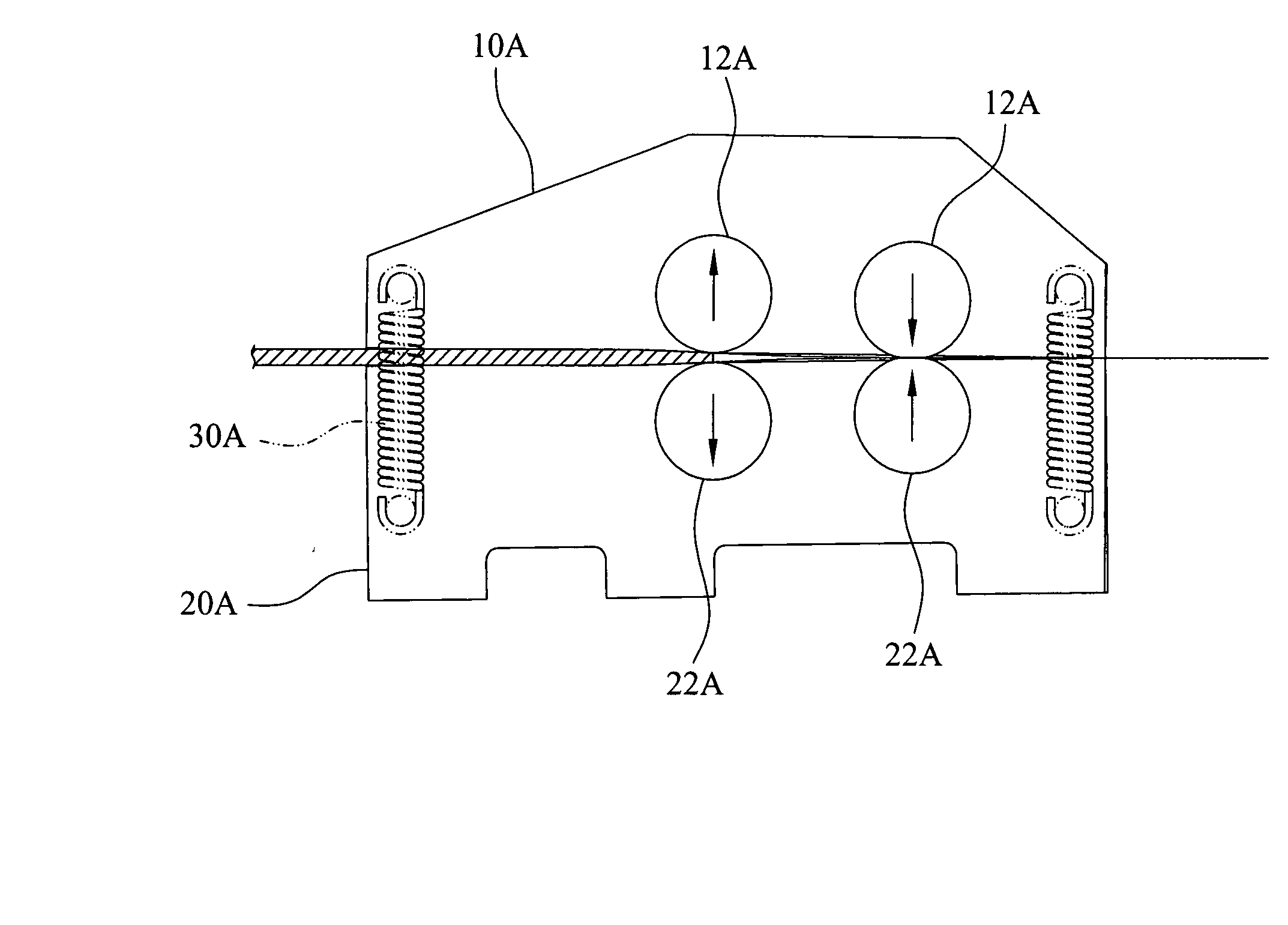
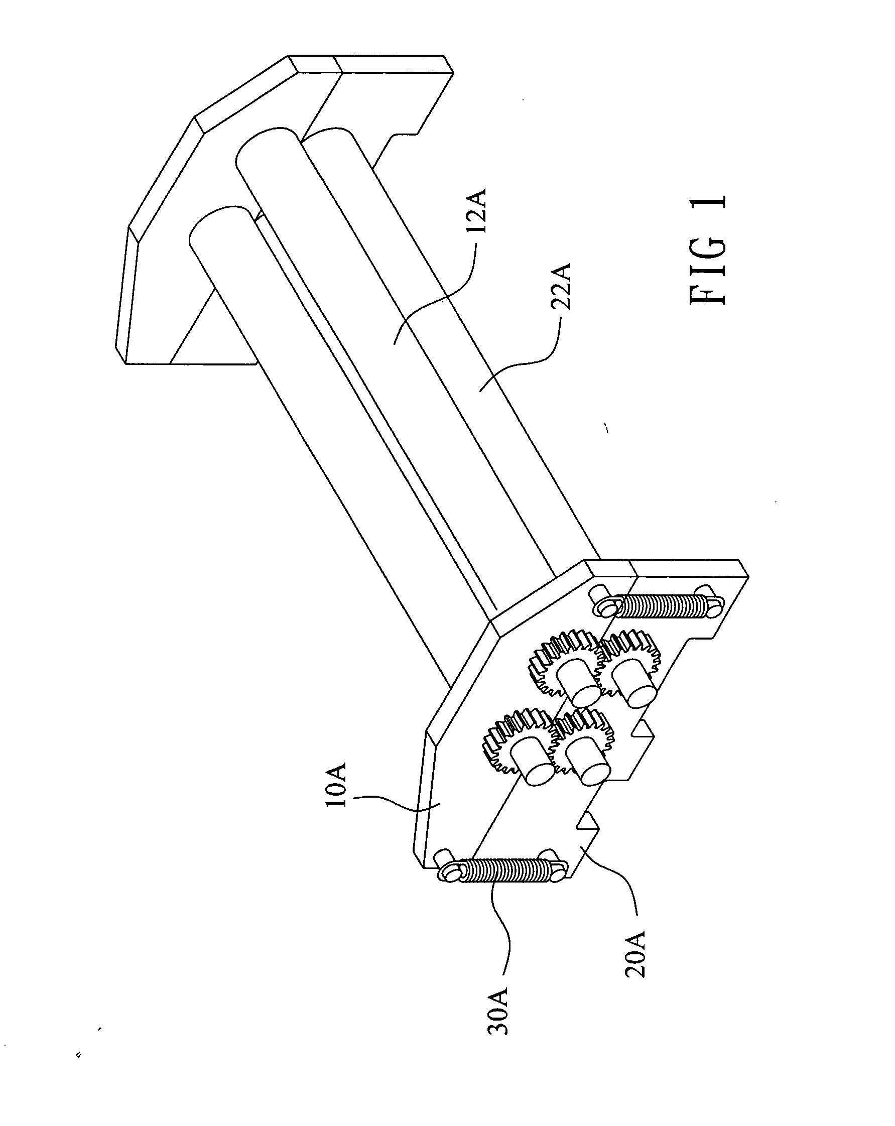
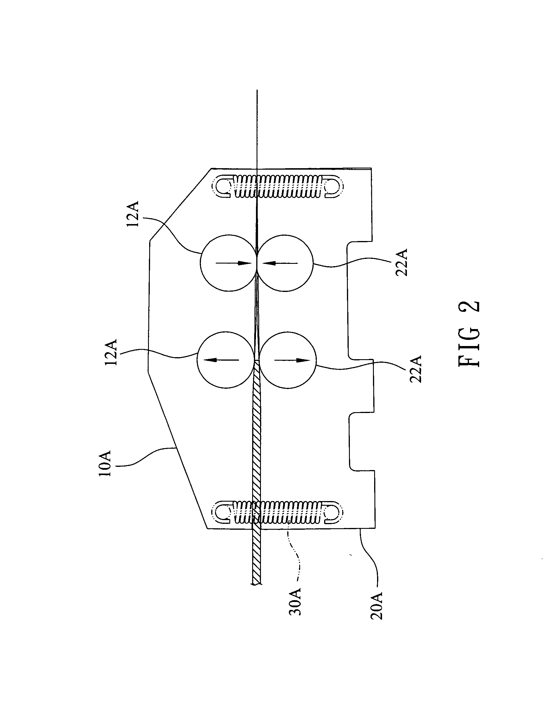
BACKGROUND OF THE INVENTION [0001] 1. Field of the Invention [0002] The present invention relates to a laminator for laminating all kinds of cards, photos, notes, leaflets, catalogues and any other document and more particularly, to such a laminator, which is stable and durable in use and, which effectively buffers the pressure from the sheet-transfer roll set during laminating operation. [0003] 2. Description of the Related Art [0004] Taiwan Patent Application No. 089217361 discloses a laminator. This structure of laminator, as shown in FIG. 1, comprises two support frame structures and a sheet-transfer roll set supported between the two support frame structures. Each support frame structure comprises an upper holder frame 10A, a bottom holder frame 20A that supports the upper holder frame 10A, and a plurality of tensile springs 30A connected between the upper holder frame 10A and the bottom holder frame 20A. When laminating a relatively thicker workpiece, the upper holder frame 10...

Claims


Application Information

Patent Timeline
IPC IPC(8): B32B37/00B30B3/04B30B15/34
CPCY10T156/1741B32B37/0053
Inventor CHOU, KUANG-HUI
Owner TEX YEAR INDS
Why Eureka
Try Eureka