Power generating structure of an exerciser

Inactive Publication Date: 2008-07-03
HSIAO SHIH WEN
View PDF14 Cites 23 Cited by
  • Summary
  • Abstract
  • Description
  • Claims
  • Application Information

AI Technical Summary

Benefits of technology

[0010]The present invention has been accomplished under the circumstances in view. It is the main object of the present invention to provide a power generating structure of an exerciser, which is easy and inexpensive to install. It is another object of the present invention to provide a power generating structure of an exerciser, which is stable and durable in use. To achieve these and other objects of the present invention, the power generating structure is installed in a wheeled exerciser, for example, a stationary bicycle, comprising a dr

Problems solved by technology

1. The system uses the driving wheel 3, the transmission belts 4, the transmission shaft 5, and the transmission wheel 6 to transfer applied force from the user to the gravity wheel 8 and the reluctance generator 9. This transmission arrangement uses a number of parts, resulting in a complicated structure and high cost.
2. Because the system uses a number of wheels (the driving wheel 3, the transmission wheel 6, and the gravity wheel 8) to transfer applied force from the user to the reluctance

Method used


Image

  • Power generating structure of an exerciser
  • Power generating structure of an exerciser
  • Power generating structure of an exerciser

Examples


Embodiment Construction

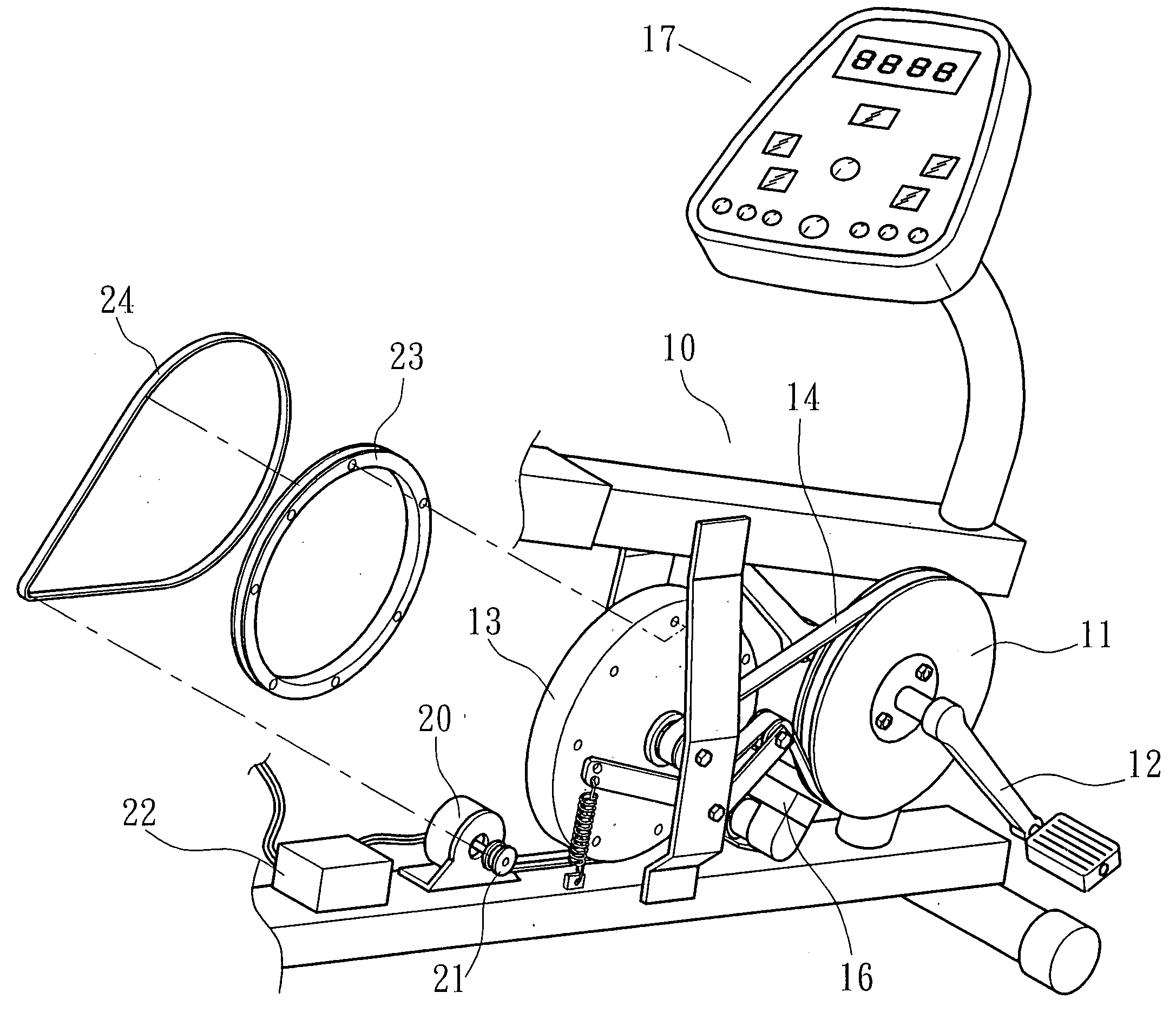
[0016]Referring to FIGS. 3˜5, a wheeled exerciser, for example, a stationary bicycle is shown mounted in the frame structure 10 thereof a driving wheel 11, a crank and pedal assembly 12 for pedaling by the user to rotate the driving wheel 11, a gravity wheel 13, a monitor 17, a transmission belt 14 coupled between the driving wheel 11 and the gravity wheel 13, and a power generator 20 for generating electricity. The gravity wheel 13 has a big idle wheel 23 fixedly fastened to one side thereof. The power generator 20 has a small idle wheel 21 fixedly fastened to one side thereof. Further, a transmission belt 24 is coupled between the big idle wheel 23 and the small idle wheel 21. Therefore, when the gravity wheel 13 is rotated by the driving wheel 11 through the transmission belt 14 during pedaling of the crank and pedal assembly 12 by the user, the power generator 20 is rotated with the small idle wheel 21 by the transmission belt 24 to generate electricity and to have generated ele...


PUM


Abstract

A power generating structure of an exerciser is disclosed to include a driving wheel, a crank and pedal assembly for pedaling by the user to rotate the driving wheel, a gravity wheel, a first transmission belt coupled between the driving wheel and the gravity wheel, a big idle wheel fixedly provided at one side of the gravity wheel, a power generator, a small idle wheel provided at one side of the power generator, and a second transmission belt coupled between the big idle wheel and the small idle wheel for driving the power generator to generate electricity upon rotation of the gravity wheel by the driving wheel.

Description

BACKGROUND OF THE INVENTION[0001]1. Field of the Invention[0002]The present invention relates to an exercising machine and more specifically, to a power generating structure of an exerciser.[0003]2. Description of the Related Art[0004]A wheeled exerciser, for example, a stationary bicycle, as shown in FIGS. 1 and 2, comprises a frame structure 1, a crank and pedal assembly 2, a driving wheel 3, two transmission belts 4, a transmission shaft 5, a transmission wheel 6, a monitor 7, a gravity wheel 8, a reluctance generator 9. When pedaling the crank and pedal assembly 2 to rotate the driving wheel 3, the transmission shaft 5 is rotated by one transmission belt 4, and the transmission wheel 6 is rotated with the transmission shaft 5 to rotate the gravity wheel 8 and the reluctance generator 9 via the other transmission belt 4, thereby causing the reluctance generator 9 to generate electricity for the monitor 7.[0005]The power generating system of the aforesaid design has numerous drawb...

Claims


Application Information

Patent Timeline
IPC IPC(8): A63B22/06
CPCA63B21/0053A63B21/225A63B2022/0652A63B2208/0238A63B22/0605A63B2021/0054A63B21/0054
Inventor HSIAO, SHIH-WEN
Owner HSIAO SHIH WEN
Why Eureka
Try Eureka