New energy turbine engine

A turbine engine and engine technology, which is applied to machines/engines, gas turbine devices, mechanical equipment, etc., can solve the problems of low fuel utilization rate, low energy utilization efficiency, incomplete combustion, etc., so as to reduce the content of harmful toxic gases and alleviate Energy stress, the effect of removing glue carbon deposits

Inactive Publication Date: 2018-02-23
福建亿谷新能源有限公司
View PDF0 Cites 8 Cited by
  • Summary
  • Abstract
  • Description
  • Claims
  • Application Information

AI Technical Summary

Problems solved by technology

[0002] Existing turbine engines work in the form of heat engines, which use a single fuel to burn and do work, and the energy utilization efficiency is low, and most of the available energy is wasted as useless heat energy
There are low engine performance, incomplete combustion, small effective working volume of the combustion chamber due to carbon deposits, colloidal carbon deposits in the combustion chamber and turbine blades, fuel adsorption carbon deposits are prone to deflagration, resulting in insufficient combustion, and carbon deposits in the injectors are also It will lead to channel blockage, jet deformation, poor atomization, increased fuel consumption, and hydrocarbons, paraffin, and colloids that cannot be completely burned in the turbine combustion chamber will be burned into colloidal carbon. Colloidal carbon has the characteristics of absorbing fuel and is used The absorbed fuel is burnt into colloidal carbon to form thicker carbon deposits, and thicker carbon deposits absorb more fuel, resulting in waste of fuel resources, resulting in accelerated deterioration of engine working conditions, engine performance, economy and use. Due to the small amount of intake air, the mixture ratio of fuel and air is not good, the combustion is not sufficient, and the tail pipe emits black smoke, which leads to the reduction of engine output power and low fuel utilization rate, which has a certain impact on energy saving and emission. limitations

Method used


Image

  • New energy turbine engine

Examples


Embodiment Construction

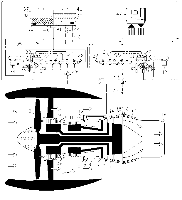
[0012] specific implementation plan

[0013] Refer to attached figure 1 :

[0014]Fuel injection system: computer ECU (47), fuel tank (37), fuel (38), fuel primary filter (39), fuel level sensor (40), fuel fine filter (34), annular fuel pipe (6), High-pressure fuel pump pressure sensor (33), fuel return pipe (36), low-pressure fuel pipe (35), high-pressure fuel pump (32), fuel common rail pipe sensor (28), fuel injection control valve (29), input high-pressure fuel pipe (30), annular fuel pipe (6), fuel injector (12).

[0015] Water injection system: computer ECU (47), water tank (46), water (45), water primary filter (44), water level sensor (41), water fine filter (19), high pressure water pump pressure sensor (20), high pressure water pump (21), high pressure water common rail pipe (22), input high pressure water pipe (26), high pressure common rail water pressure sensor (27), water injection control valve (23), output high pressure water pipe (24), water return pipe (42...


PUM


Abstract

The technology of the present invention is used in a new energy turbine engine. The air of the turbine engine is mixed with fuel in the combustion chamber. After ignition, the fuel burns and explodes. Water spray, water atomized micro-particles meet hot high temperature, after secondary gasification, the volume expands rapidly, enhances the driving force of the turbine, converts chemical energy into heat energy after combustion, and then converts heat energy into mechanical energy, explosive gasification and expansion As the gas increases suddenly, the power to push the turbine blades also increases, which enhances the reaction thrust of the engine. The water injection of this technology has a significant promotion effect on the turbine engine.

Description

technical field [0001] The patented technology of the present invention relates to a new energy turbine engine, high-pressure water injection in the combustion chamber of the turbine power machine, between the turbine blades, and in the tail nozzle, which has energy saving and environmental protection and equipment for improving the power performance of the engine. Background technique [0002] Existing turbine engines use a heat engine to do work. They use a single fuel to burn and do work. The energy utilization efficiency is low, and most of the available energy is wasted as useless heat energy. There are low engine performance, incomplete combustion, small effective working volume of the combustion chamber due to carbon deposits, colloidal carbon deposits in the combustion chamber and turbine blades, fuel adsorption carbon deposits are prone to deflagration, resulting in insufficient combustion, and carbon deposits in the injectors are also It will lead to channel bloc...

Claims


Application Information

Patent Timeline
Patent Type & Authority Applications(China)
IPC IPC(8): F02C3/30
CPCF02C3/30F02C3/305
Inventor 林寒清林剑豪
Owner 福建亿谷新能源有限公司
Why Eureka
Try Eureka