Two-way coupling apparatus and method

a two-way coupling and apparatus technology, applied in the direction of interengaging clutches, friction clutches, clutches, etc., can solve the problems of material loss, prone to wear, failure,

Inactive Publication Date: 2006-07-04
HONDA MOTOR CO LTD
View PDF16 Cites 5 Cited by
  • Summary
  • Abstract
  • Description
  • Claims
  • Application Information

AI Technical Summary

Benefits of technology

[0015]According to one aspect of this method, rotation of the first rotatable member in the first direction drives the contact end of the catch mechanism into contact with the inner surface of the second rotatable member, and causes the contact end to move along the inner surface and into engagement with the second recess of the second rotatable member. According to another aspect of this method, the contact end of the catch mechanism maintains contact with the first recess of the first rotatable member while engaging the second recess of the second rotatable member to assist in retaining the contact end in seating engagement with the second recess during rotation of the first rotatable member in the first direction.
[0016]Therefore, it is an object to provide a novel coupling device and method for coupling an input component to an output component which, when de-coupled, permits free rotation of the output component in both the forward and reverse directions.

Problems solved by technology

Clutches of the type disclosed in U.S. Pat. Nos. 4,909,365 and 5,307,911 in which engagement requires the development of friction use several components that, in operation, are subjected to large amounts of heat energy and impact, and hence are prone to wearing, loss of material, and failure.

Method used


Image

  • Two-way coupling apparatus and method
  • Two-way coupling apparatus and method
  • Two-way coupling apparatus and method

Examples


Embodiment Construction

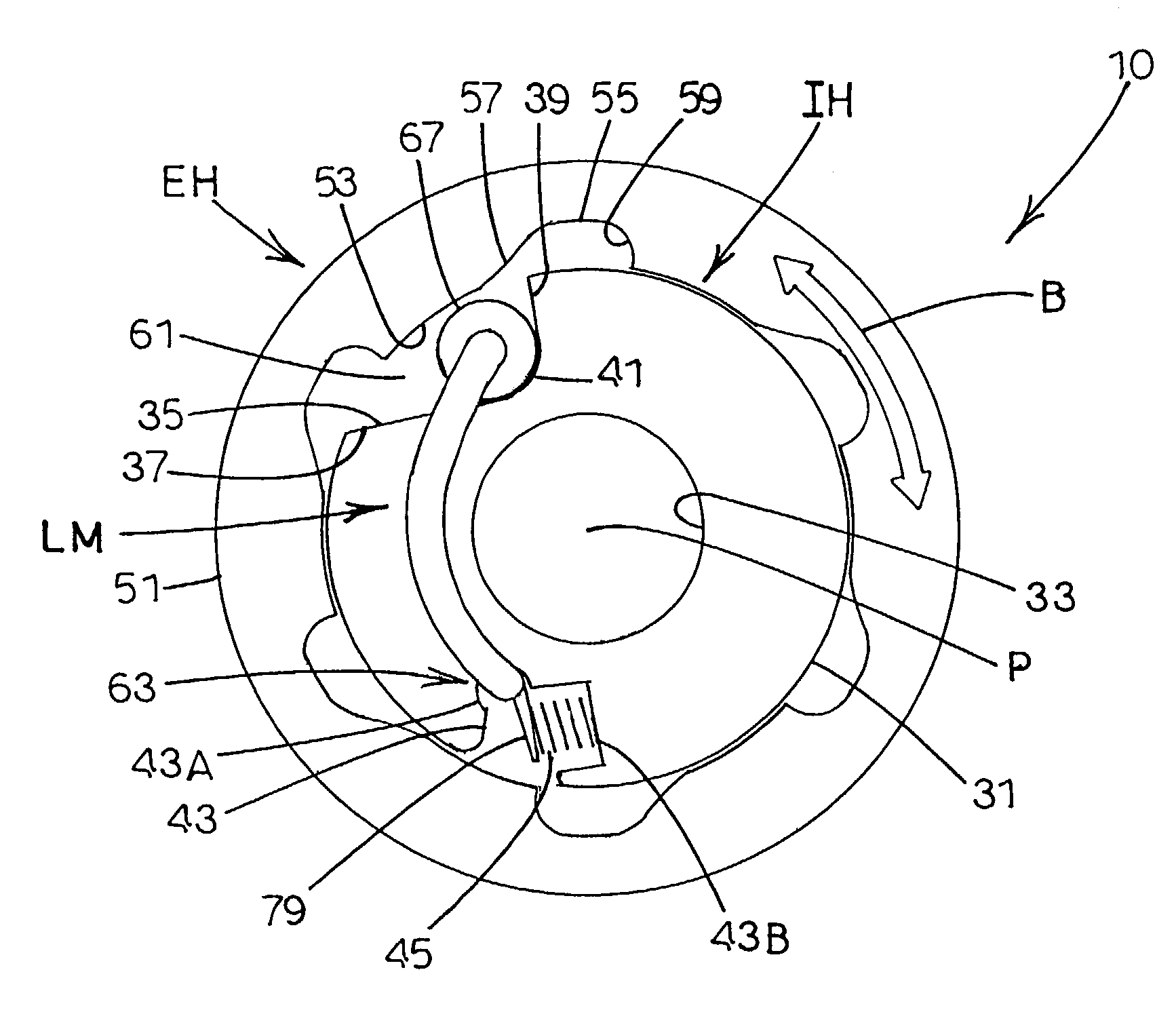
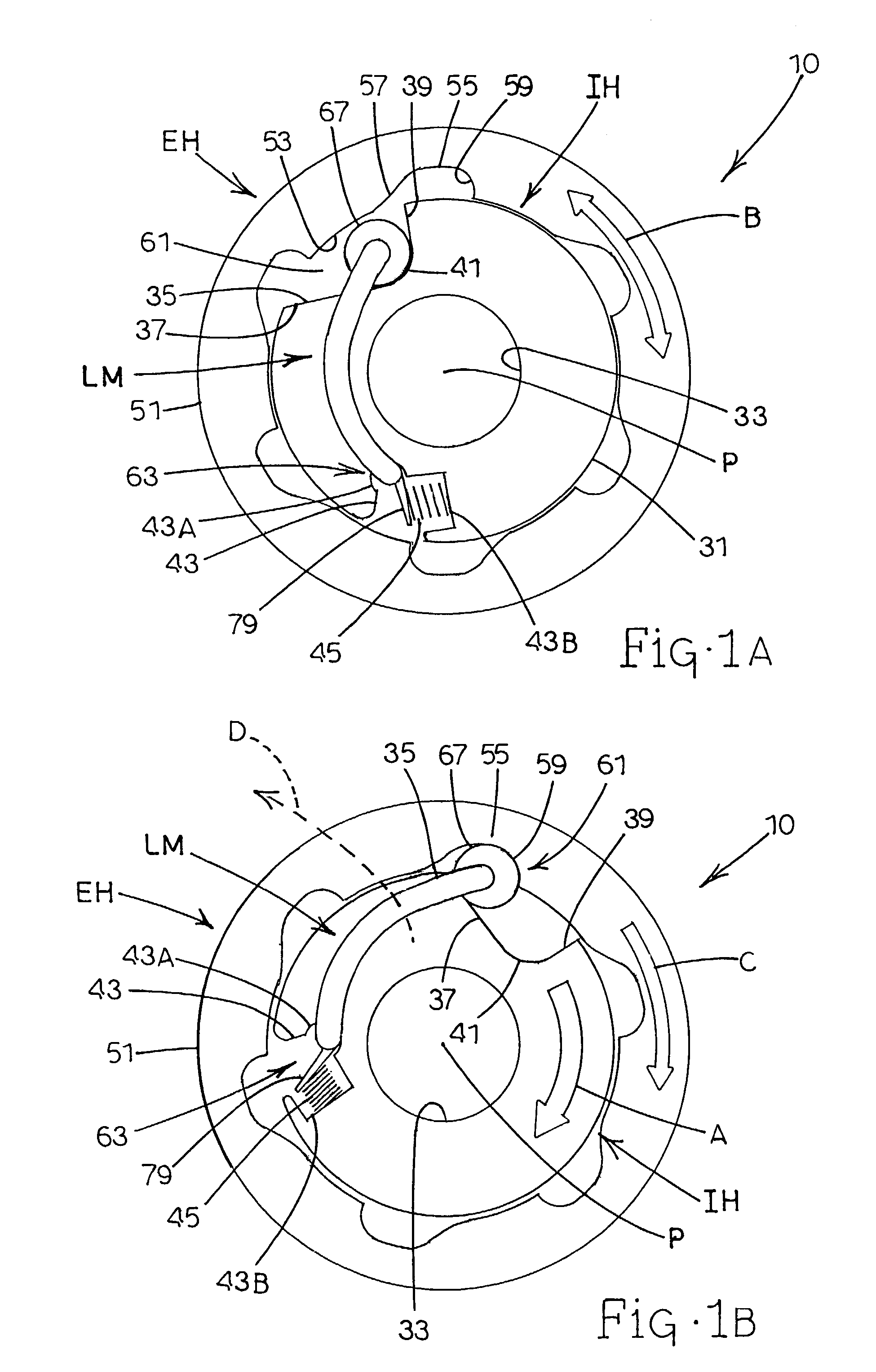
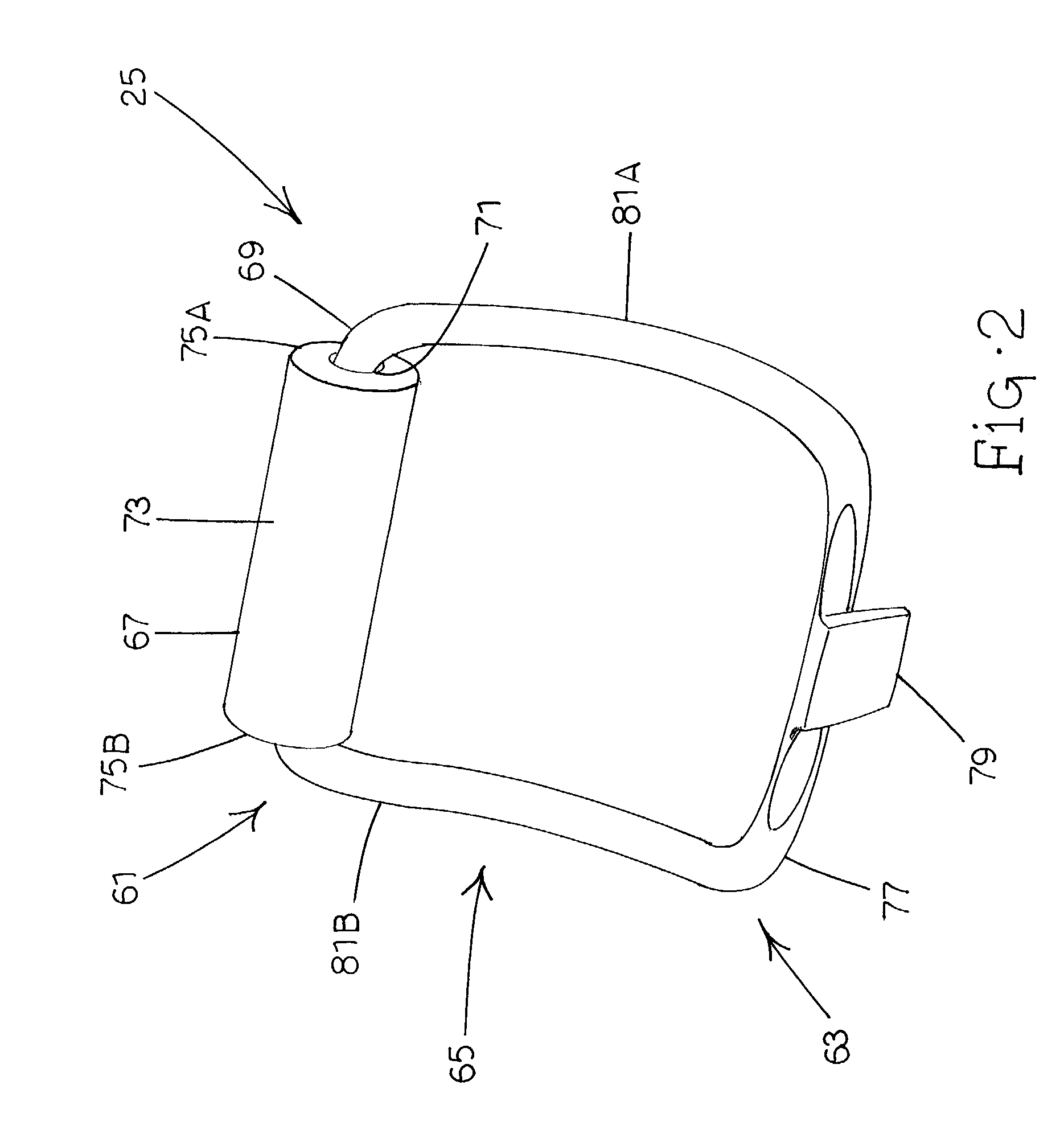
[0023]Referring now to FIGS. 1A and 1B, a coupling apparatus is shown in a preferred embodiment generally designated 10. Coupling apparatus 10 comprises an internal hub generally designated IH; an external hub generally designated EH; and a locking or catch mechanism, generally designated LM. Coupling apparatus 10 is movable between a de-coupled or disengaged state and a coupled or engaged state. FIG. 1A illustrates the de-coupled state in which internal hub IH and external hub EH are not mechanically connected to each other. FIG. 1B illustrates the coupled state in which internal hub IH and external hub EH are connected to each other by means of locking mechanism LM, as described in more detail below.

[0024]Internal hub IH rotates about a central axis, represented by a point P in FIGS. 1A and 1B. In certain embodiments of the invention, internal hub IH is mated to a powered input shaft that rotates only in one direction, represented by arrow A in FIG. 1B. The sense of directional ar...


PUM


Abstract

A centrifugally actuated coupling apparatus having an internal hub, an annular rotatable external hub coaxially disposed about the internal hub, and a locking element. The internal hub is rotatable about an axis, and includes an outer circumferential surface and a first recess formed on the outer surface. The external hub includes an inner circumferential surface and at least one circumferentially spaced second recess formed on the inner surface. The locking element includes a pivot end and a contact end. The pivot end is pivotally retained by the internal hub, and the contact end movably contacts the first recess. The contact end is pivotable radially outwardly by centrifugal force into engagement with one of the second recesses in response to rotation of the internal hub in a forward direction with respect to the external hub.

Description

TECHNICAL FIELD[0001]The present invention is generally directed to coupling devices for use in selectively transmitting rotational power (e.g., torque) from a rotating input component to a rotating output component. More particularly, the present invention is directed to a coupling apparatus and method that when de-coupled permits rotation of the output component in both the forward and reverse directions.BACKGROUND ART[0002]Mechanical couplers such as clutches are used in a wide variety of applications to selectively connect and disconnect a driving mechanism to and from a driven mechanism. Typical uses include automotive applications such as vehicular transmissions and self-propelled applications such as riding or walk-behind lawn mowers and other mobile powered equipment. The driving mechanism supplies input power and the driven mechanism receives the input power to provide an output response. When a clutch is positioned in a coupled state, its associated driving mechanism is me...

Claims


Application Information

Patent Timeline
Patent Type & Authority Patents(United States)
IPC IPC(8): F16D23/10F16D43/14
CPCF16D43/14F16D2043/145
Inventor WIANS, JEFFREY A.
Owner HONDA MOTOR CO LTD
Why Eureka
Try Eureka