
Radio resource management

a radio resource controller and resource management technology, applied in the field of radio resource managers, can solve the problems of difficult border management of radio resource controllers, limited resource management functions, and small amount of information that is possible to be exchanged between different radio resource controllers

Inactive Publication Date: 2006-07-04
QUALCOMM INC
View PDF10 Cites 125 Cited by
  • Summary
  • Abstract
  • Description
  • Claims
  • Application Information

AI Technical Summary

Benefits of technology

[0007]It is an aim of embodiments of the present invention to address one or more of the problems discussed above.

Problems solved by technology

The efficiency of the resource management functions is limited by the area under the control of the radio resource controllers of the respective systems.
The prior art arrangement with the resources being controlled by the radio network controllers of the respective systems is a particular problem with the making of handover decision between the systems.
This is because the information that can be taken into account to perform the handover is limited to the resources under the control of each radio resource controller.
Within a single system, the main limitation is the small amount of information that is possible to be exchanged between different radio resource controllers.
This makes the management of the radio resources in the radio resource controller border areas difficult as the knowledge of the cells under control of the neighboring radio resource controller(s) is limited.
In a multi-system environment the information available from the cells of another radio access system is even more restricted and there is no standardised way to check the status of a cell in another system.
An additional problem is that the separate operation and maintenance of multiple systems is not cost-efficient and could result in low resource usage and poor network quality.
Contrary to existing 2nd generation networks a continuous coverage or Quality of Service (QoS) cannot be guaranteed for all services everywhere in the cell because of higher signal-to-interference ratios demanded by high bit rate 3rd generation services.
If a cell to which a call is allocated, handed over or the like does not support the required quality of service, this may mean that the service in question cannot be supported or supported adequately.

Method used


Image

  • Radio resource management
  • Radio resource management
  • Radio resource management

Examples


Embodiment Construction

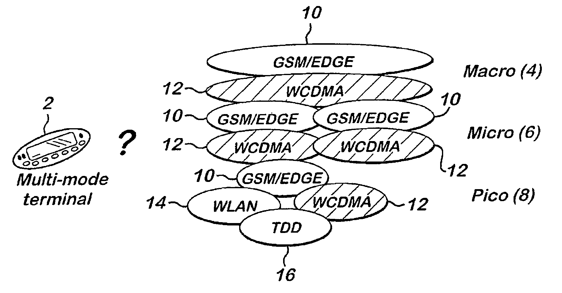
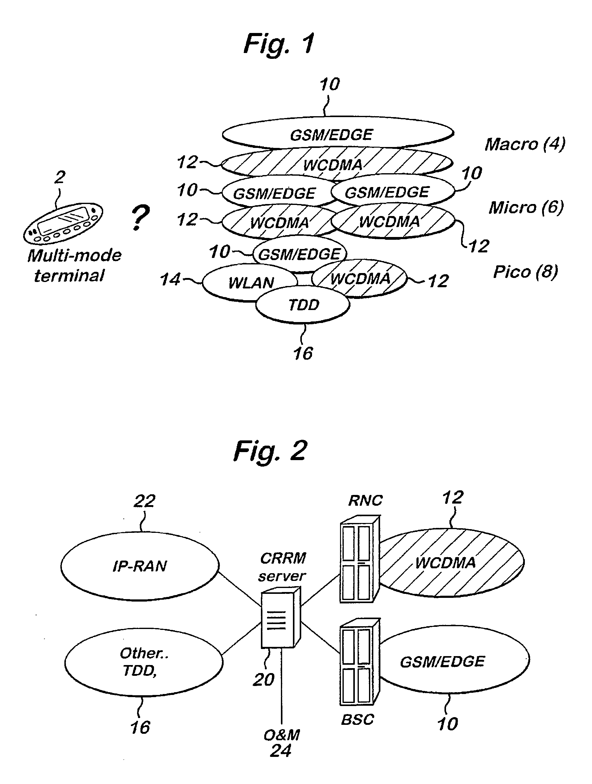
[0026]Reference is made to FIG. 1 which shows a network comprising a plurality of different radio access technologies. A mobile station 2 or the like user equipment is able to use more than one radio access technology. It should be appreciated that the mobile station may in fact be stationary and may for example be a PC, personal digital assistant (PDA) or the like.

[0027]In the example shown, the radio access technologies are macro, micro or pico systems 4, 6 or 8 respectively. These different systems will have different sizes of cells with macro cells being much larger than pico cells. Usually the coverage area of one macro cell overlaps with several micro and / or pico cells. Different radio access technology systems can also be used within the macro, micro and pico systems. In the example shown, the different radio access technologies comprise GSM / EDGE 10, WCDMA 12, WLAN 14 (wireless local area network) or TDD 16 (time division duplex). It should be appreciated that this is by way ...


PUM


Abstract

A method for use in a network covering a region, said region comprising a plurality of areas, a user being assigned to at least oen of said area and having associated therewith a plurality of candidate areas to which the user may be assigned, said method comprising the steps of receiving information identifying said plurality of candidate areas; estimating for each candidate area a parameter, said parameter assuming that said user is assigned to said candidate area; and prioritising said plurality of candidate areas which takes into account the estimated value of said parameter.

Description

FIELD OF THE INVENTION[0001]The present invention relates to a radio resource manager and a method of radio resource management.BACKGROUND OF THE INVENTION[0002]It has been proposed that in the future wireless communications networks will consist of more than one radio access technology, such as WCDMA (wideband code division multiple access), GSM / EDGE (global system for mobile communication) or the like. By exploiting the different radio access technologies, the network as a whole can take advantage of the coverage and capacity characteristics of each technology. This can result in a more economic solution and provide the most appropriate radio bearers for a variety of different services.[0003]In the known radio access networks the management of the radio resources between the systems is performed in a distributed way. The radio network controllers of the different systems manage the radio resources of each system independently. The efficiency of the resource management functions is...

Claims


Application Information

Patent Timeline
Patent Type & Authority Patents(United States)
IPC IPC(8): H04Q7/20H04L12/56H04L12/46H04W16/14H04W28/18H04W36/26H04W48/18
CPCH04W16/14H04W28/18H04W72/042H04W48/18H04W72/04H04W36/26H04W36/24H04W72/23
Inventor RAMOS, GABRIELSALMENKAITA, MATTILONGONI, FABIOD'ARGENCE, FRANCOISHALONEN, TIMOMELERO, JUANHAKALIN, PETTERTOLLI, ANTTICORTES, JOSE ANTONIOKANGAS, ARTOHOLMA, HARRI
Owner QUALCOMM INC
Learn More