Silencer for perforated plate flow conditioner

a flow conditioner and perforated plate technology, applied in the direction of valve details, pipes, mechanical equipment, etc., can solve the problems of unwanted noise generation, noise generation, and detrimental aspects of perfroated plates

Inactive Publication Date: 2006-07-11
SAWCHUK BLAINE DARREN +1
View PDF17 Cites 46 Cited by
  • Summary
  • Abstract
  • Description
  • Claims
  • Application Information

AI Technical Summary

Problems solved by technology

Noise generation is a detrimental aspect of perfroated plates.
When fluid flows past a perforated plate, which can be a disk containing holes of any type of diameter, array, or configuration, noise is generated.
The noise generation is a normal physical characteristic of the fluid flow case, but it is a detrimental attribute which can in some cases offset the positive measurement effects of the perforated plate flow conditioner.
The undesirable noise is generated by harmonic interaction between the hole, fluid jets downstream of the screen, a flat spot of the plate on a rear section between the holes, and the location of the impact point of the fluid jets, which is a coalescing point.
This noise is detrimental to flow meter performance and is environmentally unacceptable.
Thus, flowmeters such as disclosed in U.S. Pat. No. 6,647,806, which is incorporated herein by this reference, which use a turbulence conditioner for use with transit time ultrasonic flowmeters, suffer from decreased performance due to the noise generated by the flow conditioner.
However, this silencer, in addition to being expensive, is passive, and converts the noise generated into heat after the fact.
This silencer is prone to self-destruction because the gas velocities in the pipe are large, and damage protruding devices like this device.
Rounding the leading edge of the perforated plate holes increased the noise generation significantly.

Method used


Image

  • Silencer for perforated plate flow conditioner
  • Silencer for perforated plate flow conditioner
  • Silencer for perforated plate flow conditioner

Examples


Embodiment Construction

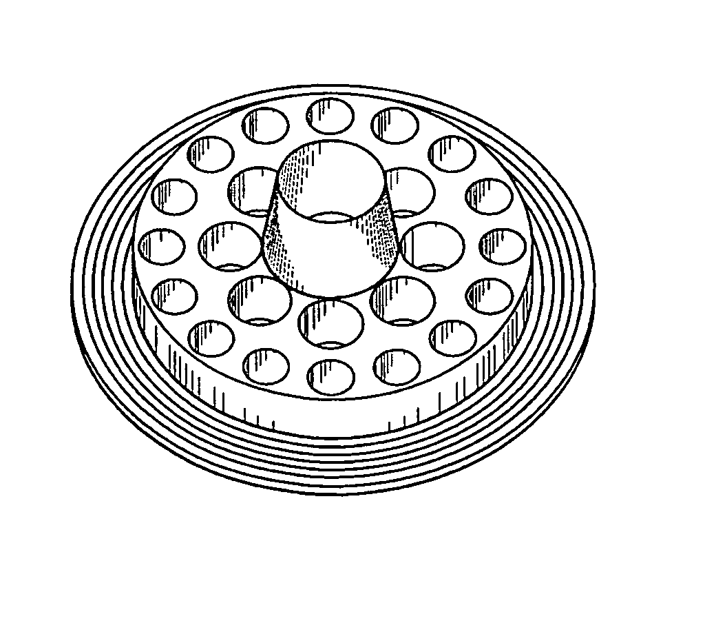
[0059]Referring now to FIG. 2, a perforated plate flow conditioner 9 includes a single solid conical acoustic feedback interference device 20 having an upstream end 22 rigidly attached to the downstream side 15 of the perforated plate flow conditioner 9. The upstream end 22 covers substantially all of the the flat spot 18 between two adjacent holes on the downstream side 15. The volume of a downstream end 24 of the acoustic feedback interference device is less than the volume of the upstream end 22. In a preferred embodiment, the acoustic feedback interference device 20 has a conical shape. However, the axial cross-sectional view of the acoustic feedback interference device 20 can also have a rectangular or cylindrical shape. In the preferred embodiment, the distance 26 between the upstream end 22 and the downstream end 24 is 0.362 of the diameter of the perforated plate flow conditioner 9.

[0060]Referring now to FIG. 3, in an alternate embodiment, the perforated plate flow condition...


PUM


Abstract

A perforated plate flow conditioner includes a single acoustic feedback interference device having an upstream end attached to a downstream side of the perforated plate. The upstream end covers substantially all of the downstream side of the perforated plate between two adjacent holes. The volume of a downstream end of the interference device is less than the volume of the upstream end. In another embodiment of the invention, the upstream end of a single acoustic feedback interference device covers substantially all of the spaces between a central hole and all of the surrounding adjacent holes. In another embodiment of the invention, all of the spaces between adjacent holes are substantially covered by upstream ends of acoustic feedback interference devices.

Description

CROSS-REFERENCES TO RELATED APPLICATIONS[0001]This application claims the benefit of U.S. Provisional Application No. 60 / 553,952, filed on Mar. 18, 2004.STATEMENT REGARDING FEDERALLY SPONSORED RESEARCH OF DEVELOPMENT[0002]Not applicable.FIELD OF THE INVENTION[0003]The present invention relates to pipeline perforated plate noise elimination generally, and in particular relates to the elimination of noise generated by the special application of a perforated plate flow conditioner to assist in flow measurement.BACKGROUND OF THE INVENTION[0004]Specially devised screens are used in the pipeline industry to reconfigure the fluid flow profile in the pipeline. When used to correct the fluid flow profile in the pipe they are referred to as perforated plate flow conditioners. An example of such a flow conditioner is the invention described in U.S. Pat. No. 5,762,107, which is incorporated herein by this reference. That patent disclosed adding vanes parallel to the flow, both upstream and down...

Claims


Application Information

Patent Timeline
Patent Type & Authority Patents(United States)
IPC IPC(8): F15D1/00F15D1/02F16K47/08F16K47/14
CPCF15D1/02F16K47/14F16K47/08
Inventor SAWCHUK, BLAINE DARRENSAWCHUK, DALE PETER
Owner SAWCHUK BLAINE DARREN
Why Eureka
Try Eureka