
Tone wheel testing apparatus and its test method

a testing apparatus and test method technology, applied in the direction of mechanical equipment, instruments, code conversion, etc., can solve the problems of insufficient rigidity, inconvenient measurement execution, and interruption of accurate magnetic detection

Active Publication Date: 2006-07-11
UCHIYAMA MFG
View PDF4 Cites 0 Cited by
  • Summary
  • Abstract
  • Description
  • Claims
  • Application Information

AI Technical Summary

Benefits of technology

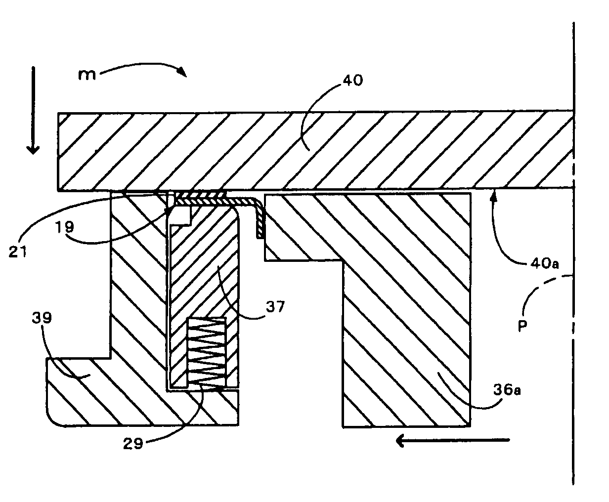
[0007]Considering the above-mentioned problems, the object of the present invention is to provide a tone wheel testing apparatus and the test method in which measurement of the magnetic force can be carried out under such conditions that the tone wheel surface doesn't have ups and downs and distortion in the circumferential direction and an appropriate gap between the tone wheel and the sensor is kept at any position in the circumferential direction.
[0008]According to the present invention the above-mentioned object is achieved, by the rotational speed of the tone wheel per unit time being measured by a magnetic testing sensor fixed with a predetermined gap apart from the tone wheel while rotating an annular object to be tested with the tone wheel made of a ring-like magnetic material around the rotary axis, thereby determining the quality of the tone wheel.

Problems solved by technology

However, according to such a prior test apparatus, it is not useful that the measurement isn't executed in such a manner that the space (gap) between the tone wheel and the sensor is accurately set at a regular value in order to correctly test the magnetic force of the tone wheel and the pitch of each north or south pole.
Namely, if there are ups and downs on the tone wheel in the circumferential direction, the space between the tone wheel and the sensor is changed during the rotation and the changing of the magnetic force should cause interruption of the accurate magnetic detection.
Although the tone wheel is generally reinforced with a core member of the seal ring, the core member is a thin steel plate which has the section like the letter “L” doesn't have enough rigidity.
Therefore, it is difficult to accurately set up the ups and downs of the tone wheel in the circumferential direction or the appropriate gap for the sensor accompanied with rotation only by simply holding the seal ring.

Method used


Image

  • Tone wheel testing apparatus and its test method
  • Tone wheel testing apparatus and its test method
  • Tone wheel testing apparatus and its test method

Examples


Embodiment Construction

[0023]The embodiments of the present invention are explained referring to the attached drawings.

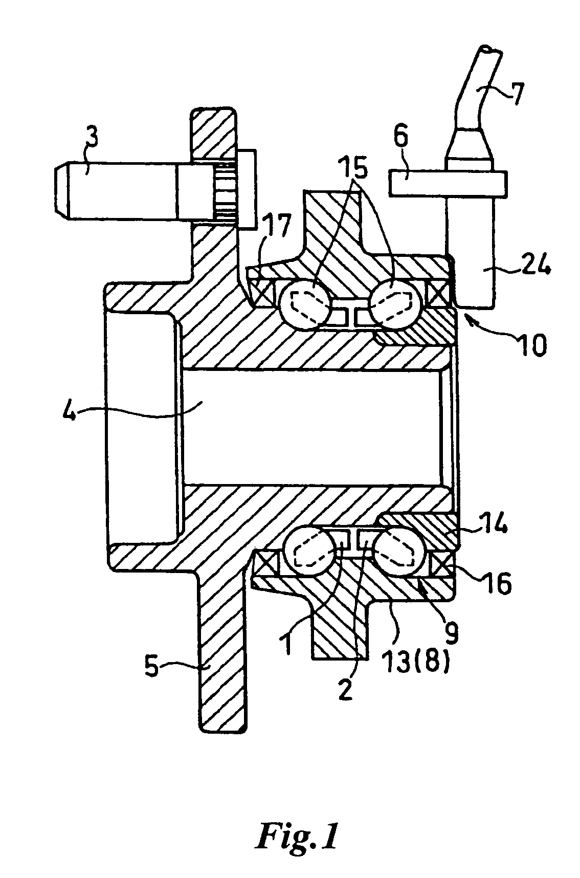
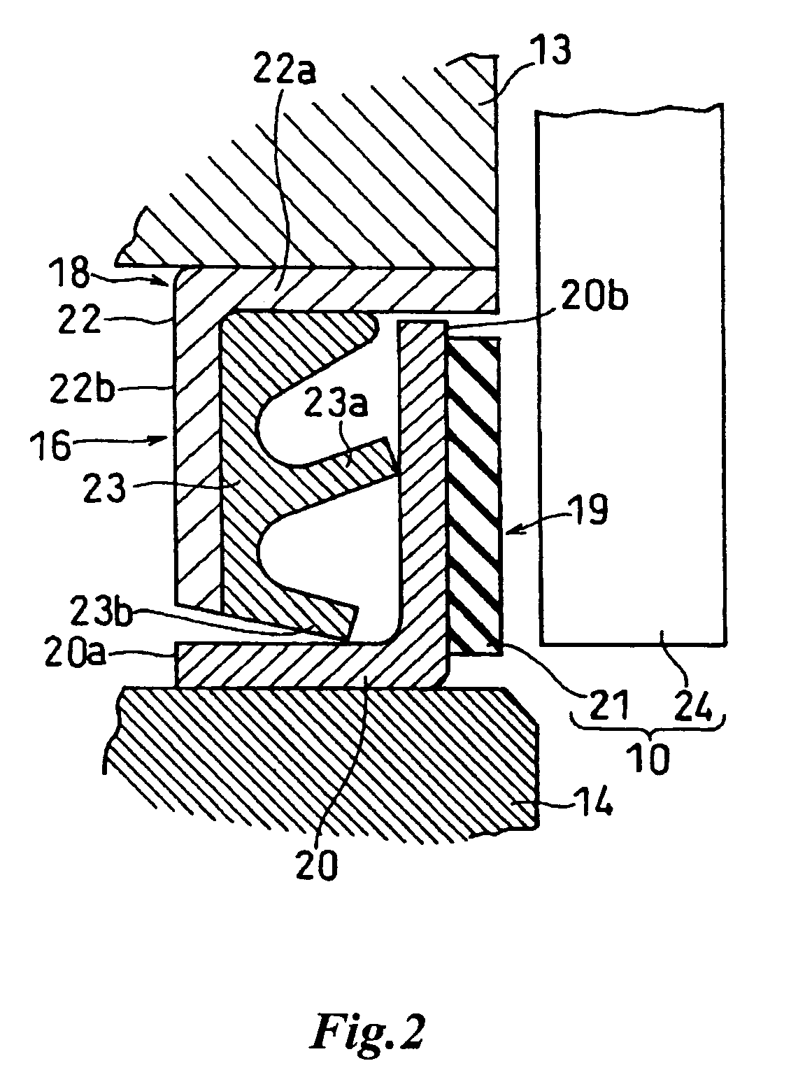
[0024]FIG. 1 shows the construction of an angular type bearing (rolling bearing unit) 9 rotatably supporting a driving wheel such as a wheel of automobiles or thereabouts. FIG. 2 shows an enlarged sectional view of an inner seal ring 16 incorporated into the bearing 9.

[0025]The bearing 9 is constructed so as to rotatably support a hub 5 constituting a part of the wheel which is a rotary side from a hub carrier 8 which is a non-rotary side as shown in FIG. 1. The bearing 9 comprises an outer ring 13 which is press-fitted in the hub carrier 8, an inner ring 14 integrated in the inside of the hub 5, balls 15 which are rolling elements with two rows at both sides between the hub 5, namely the inner ring 14, and retainers 1, 2 for arranging the balls 15 evenly spaced in the circumferential direction. An inner seal ring 16 is provided at the gap between the outer ring 13 and the inner ring 14 a...


PUM


Abstract

Tone wheel testing apparatus and the test method using the apparatus are disclosed. Tone wheel testing apparatus comprising a surface adjusting means for holding in the horizontal position an annular object to be tested to which a tone wheel is attached, the means comprising a pair of pressing members between which the object is held, and the one of the pressing members having a reference surface with which the tone wheel is contacted in order to make the tone wheel align in the rotary axis direction of the object, a rotatable chucking means for seizing the object so as to make the center of the object align with its rotary center when the object is held by the surface adjusting means, and a magnetic testing sensor disposed adjacent to the tone wheel of the object so as to face each other. According to which, the up and down appear on the tone wheel surface in the circumferential direction are corrected and the gap between the testing sensor and the tone wheel is accurately maintained, thereby enabling an appropriate setting arrangement of tone wheel for accurate measurement of the array pitch of each pole and the magnetic force.

Description

FIELD OF THE INVENTION[0001]The present invention relates to a tone wheel testing apparatus and its test method, specifically to a tone wheel testing apparatus and its test method for measuring and testing the pitch of a magnetic pole array and the intensity of magnetic fields from the magnetic pole array of the tone wheel which is incorporated into a bearing for rotatably supporting the wheel in the suspension system of a vehicle, and which detects the rotation speed of the wheel.PRIOR ART[0002]A bearing provided with a tone wheel for rotatably supporting the wheel is incorporated into the suspension system of a vehicle. The bearing and a sensor attached onto a fixed member of the suspension constitute en encoder to detect the rotational speed of the wheel to control the Anti Lock Brake System (ABS) or the Traction Control System (TCS). The tone wheel is integrally provided for a rotary member at the seal for blocking off the end of the bearing, and such an example is disclosed in ...

Claims


Application Information

Patent Timeline
Patent Type & Authority Patents(United States)
IPC IPC(8): G01P3/48F16C19/52F16C41/00G01D5/245G01M13/04G01P3/44G01P21/02G01R33/02H03M1/22
CPCG01P21/02G01P3/443
Inventor TOMIOKA, MASANORI
Owner UCHIYAMA MFG
Learn More