Supercharge Your Innovation With Domain-Expert AI Agents!

Hot plugging device for optical transceiver modules

a technology of optical transceiver and hot plugging device, which is applied in the direction of instruments, electrical apparatus construction details, and cabinet/drawer/cabinet/drawer, etc., can solve the problems of increasing the space needed for installing optical transceiver modules, the sliding device must be continuously pushed, and the inconvenient separation of module housing and cage, etc., to achieve the effect of easy engagement or disengagement of optical transceiver modules

Inactive Publication Date: 2006-07-18
SAMSUNG ELECTRONICS CO LTD
View PDF4 Cites 18 Cited by
  • Summary
  • Abstract
  • Description
  • Claims
  • Application Information

AI Technical Summary

Benefits of technology

[0010]One object of the present invention is to provide a hot plugging device for optical transceiver modules, which is capable of easily engaging or disengaging the optical transceiver modules.
[0011]It is another object of the present invention to provide a hot plugging device for optical transceiver modules, which is capable of efficiently performing maintenance work even in a small working space.

Problems solved by technology

As described above, the conventional hot plugging device for optical transceiver modules has a problem in that the slider must be continuously pushed until the module housing is completely separated from the cage.
The separating work between the module housing and the cage is very inconvenient.
Furthermore, a space necessary to push the slider is required, which increases the space necessary to install the optical transceiver module.
Consequently, the number of the optical transceiver modules mountable on the system is limited.
In addition, the module housing or the cage may be permanently deformed or damaged when the slider is pushed to separate the module housing from the cage.

Method used


Image

  • Hot plugging device for optical transceiver modules
  • Hot plugging device for optical transceiver modules
  • Hot plugging device for optical transceiver modules

Examples


Embodiment Construction

[0021]Now, embodiments of the present invention will be described in detail with reference to the accompanying drawings. In the following, a detailed description of known functions and configurations incorporated herein will be omitted when it may obscure the subject matter of the present invention.

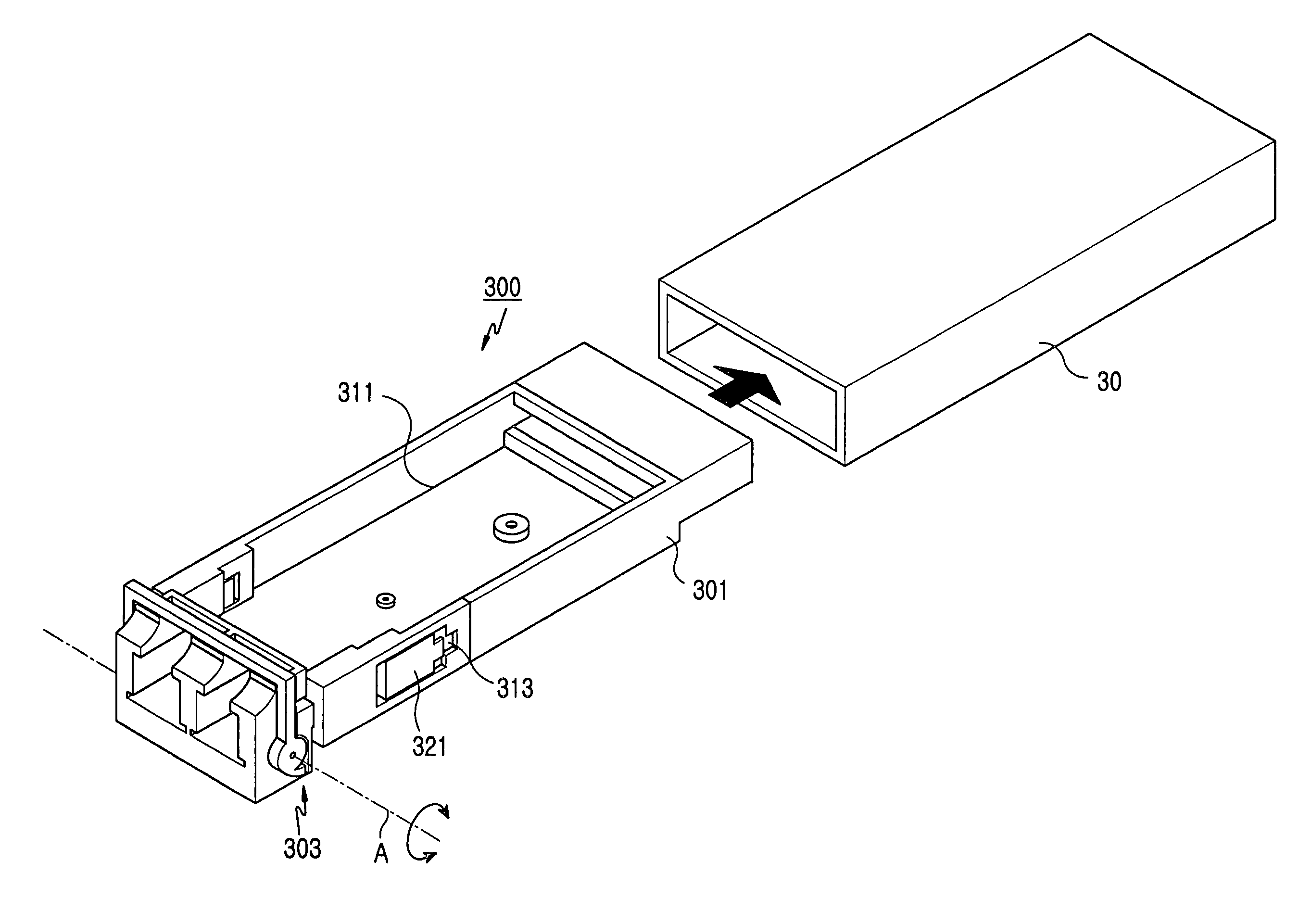
[0022]FIG. 3 is a perspective view showing a hot plugging device for optical transceiver modules according to one embodiment of the present invention. FIG. 4 is a perspective view showing a releasing unit of the hot plugging device shown in FIG. 3. As shown in FIGS. 3 and 4, the hot plugging device includes a module housing 301 having latching grooves 313 formed at both sides thereof, sliding members 321 and 323 linearly movably accommodated in the latching grooves 313, respectively, and a rotating member 303 rotatably attached to one end of the module housing 301. The module housing 301 is engaged in a cage 30, which may be mounted on a host board of an optical transmitting / receiving sys...


PUM


Abstract

Disclosed herein is a hot plugging device for optical transceiver modules. The hot plugging device comprises a module housing, latching grooves extended from prescribed positions of both sides of the module housing to one end of the module housing, respectively, sliding members extended in the longitudinal direction of the module housing and linearly movably accommodated in the latching grooves, respectively, and a rotating member rotatably attached to one end of the module housing for engaging ends of the sliding members with corresponding ends of the latching grooves, respectively, while the rotating member is placed at a prescribed angle to the longitudinal direction of the module housing. With the hot plugging device of the present invention, a locking unit of the module housing is easily released, and the release of the locking unit is maintained, whereby the module housing is easily separated from a cage. Also, a working space necessary to separate the module housing from the cage is reduced, whereby many more optical transceiver modules can be mounted. Furthermore, only latching pieces are deformed when the module housing is separated from the cage. Consequently, the present invention has an effect of preventing permanent deformation of the module housing or the cage or damage to the module housing or the cage.

Description

CLAIM OF PRIORITY[0001]This application claims priority to an application entitled “HOT PLUGGING DEVICE FOR OPTICAL TRANSCEIVER MODULES,” filed in the Korean Intellectual Property Office on Jul. 23, 2003 and assigned Serial No. 2003-50526, the contents of which ate hereby incorporated by reference.BACKGROUND OF THE INVENTION[0002]1. Field of the Invention[0003]The present invention relates to a transceiver module for optical communication, and more particularly to a hot plugging device for optical transceiver modules.[0004]2. Description of the Related Art[0005]Hot plugging devices are used for extension and maintenance of communication networks in optical transmitting / receiving systems. The hot plugging device is used to replace elements mounted on the optical transmitting / receiving system, such as optical transceiver modules, or extend the communication network without stopping the system. Because of this, such hot plugging devices are useful where system maintenance work is frequ...

Claims


Application Information

Patent Timeline
Patent Type & Authority Patents(United States)
IPC IPC(8): G02B6/36G02B6/38G02B6/42G06F1/16H05K7/14
CPCG06F1/1632G02B6/4292G02B6/3893G02B6/4246G02B6/36
Inventor LEE, YEON-JUNKIM, DAE-JIN
Owner SAMSUNG ELECTRONICS CO LTD
Features
  • R&D
  • Intellectual Property
  • Life Sciences
  • Materials
  • Tech Scout
  • Unparalleled Data Quality
  • Higher Quality Content
  • 60% Fewer Hallucinations
Learn More