
Method for winding a single coil of a coil unit for a linear motor

a technology of a linear motor and a single coil, which is applied in the direction of transformers/inductances, magnets, magnetic cores, etc., can solve the problems of serious disturbance of winding, accumulated twists, and inability to prevent component forces from accumulating with winding, and achieves low-cost and easy-to-redesign effects

Inactive Publication Date: 2006-08-01
SUMITOMO HEAVY IND LTD
View PDF5 Cites 11 Cited by
  • Summary
  • Abstract
  • Description
  • Claims
  • Application Information

AI Technical Summary

Benefits of technology

[0021]The present invention has been achieved in view of the foregoing problems. It is thus an object of the present invention to provide a technology for allowing even a type (form) of a single coil having a pair of connecting conductors bent sharply in the same direction with respect to effective conductors to be fabricated from a single wire through winding, thereby providing a low-cost easy-to-redesign single coil and a coil unit utilizing the same.

Problems solved by technology

Besides, it was impossible to prevent the component forces from accumulating with winding.
Eventually, accumulated twists occurred inevitably with the result of seriously disturbed winding which could not be contained in an intended shape.

Method used


Image

  • Method for winding a single coil of a coil unit for a linear motor
  • Method for winding a single coil of a coil unit for a linear motor
  • Method for winding a single coil of a coil unit for a linear motor

Examples


Embodiment Construction

[0058]Hereinafter, preferred embodiments of the present invention will be described in detail with reference to the accompanying drawings.

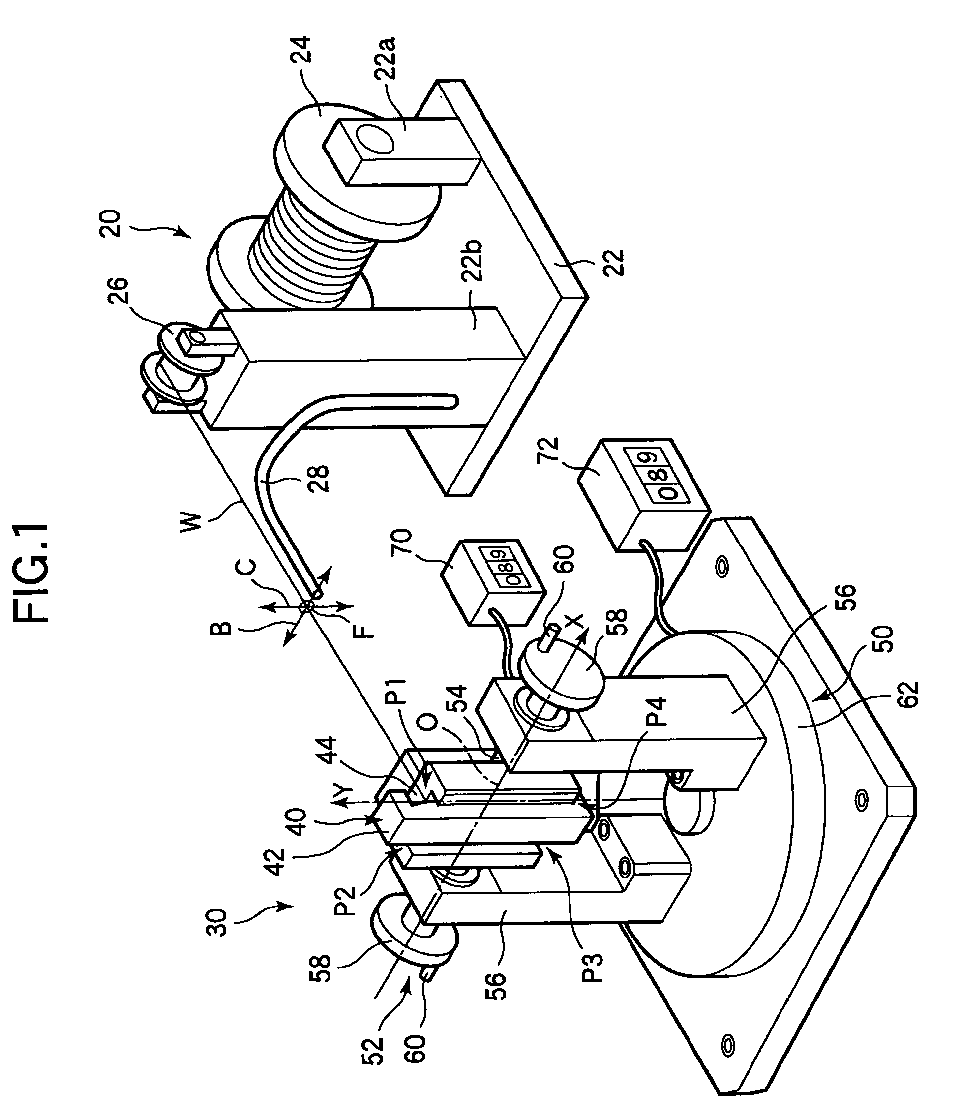
[0059]FIG. 1 schematically shows a winding device for a single coil of a coil unit for a linear motor according to the present invention.

[0060]A single coil 12 to be wound by this winding device basically has the same fundamental shape as that of the single coil 2 according to Japanese Patent Application Laid Open No. 2001-67955 which has been described in conjunction with FIGS. 10A–10C. Thus, in the following description, the parts having identical or similar functions to those of the single coil 2 will be designated by 10-odd numerals having the same last one figures. That is, the entire single coil 12 is shaped like a generally rectangular ring. Opposed two sides of this rectangular function as effective conductors 14, which contribute to producing a thrust in the moving body of a linear motor. The other two opposed sides function as connecting...


PUM

PropertyMeasurementUnit
conductiveaaaaaaaaaa
speedaaaaaaaaaa
magnetic forceaaaaaaaaaa

Abstract

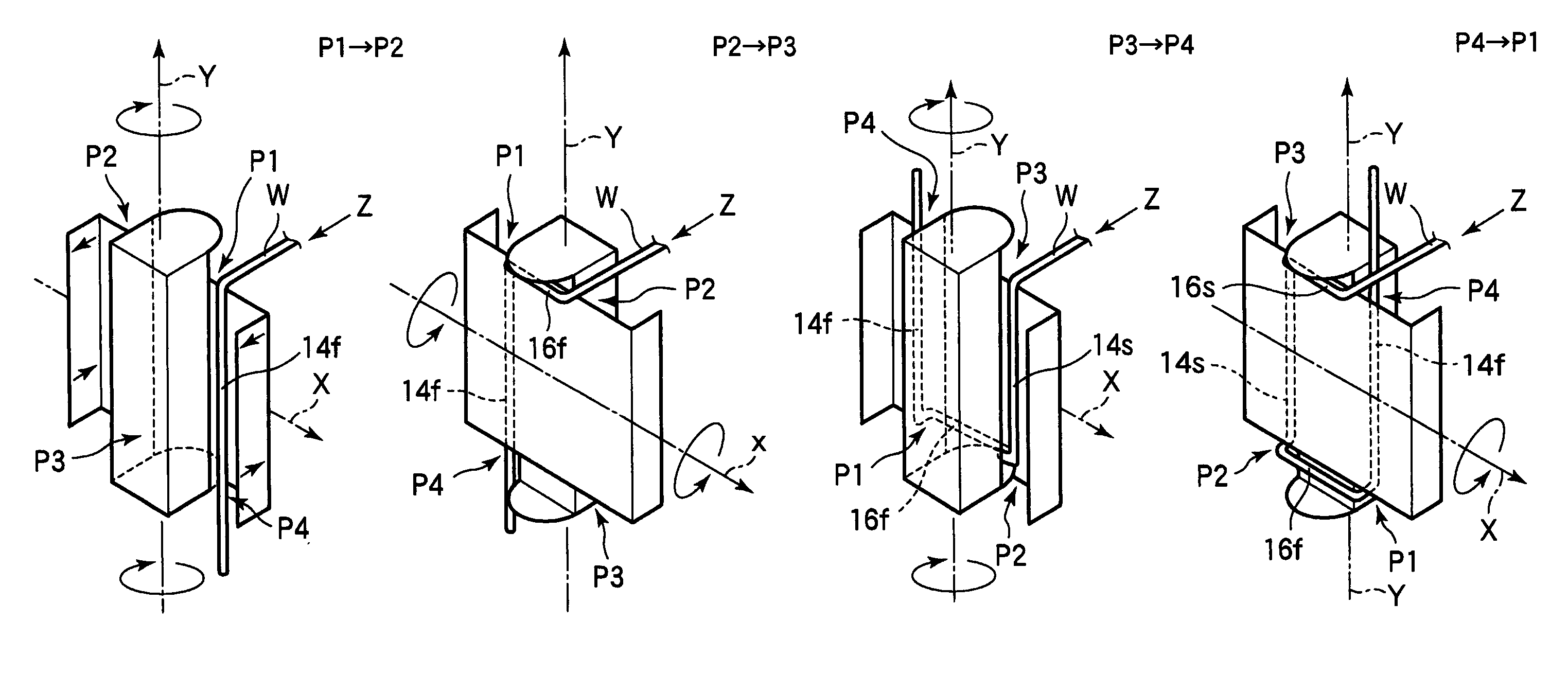
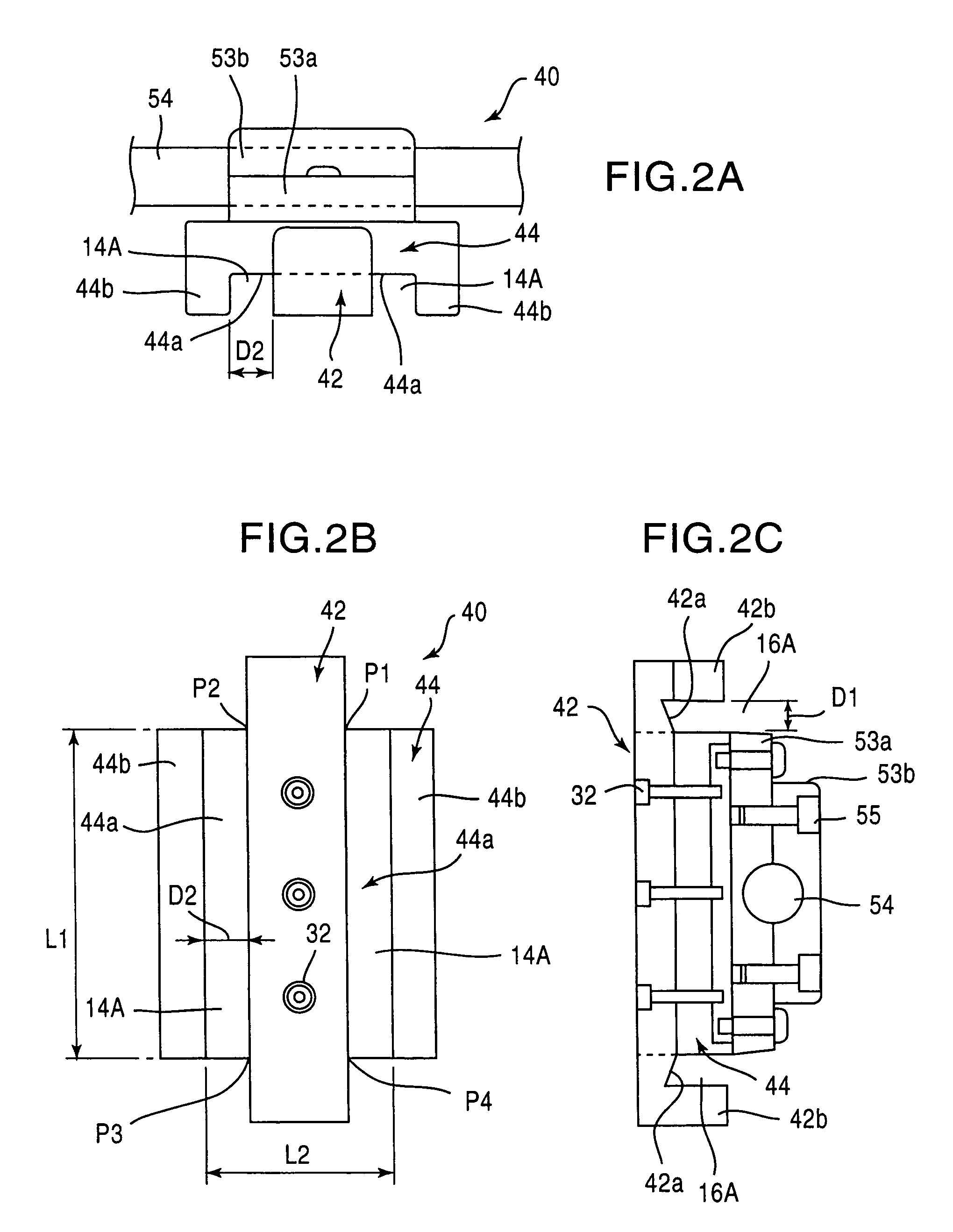
A rectangular single coil of a coil unit for a linear motor is fabracated by winding a single conductive wire. A winding former having locks for a conductive wire at positions corresponding to vertices of the rectangular single coil is rotated by 180 degrees about an X-axis, by 180 degrees about a Y-axis, alternately by first and second rotating mechanisms. Thereby, a single conductive wire fed out in the direction of a Z-axis from a conductive wire feeding out machine is wound while locked to the locks of the winding former in succession.

Description

[0001]This is a division of application Ser. No. 10 / 083,686 filed Feb. 27, 2002, now U.S. Pat. No. 6,644,584.BACKGROUND OF THE INVENTION[0002]1. Field of the Invention[0003]The invention relates to a technology for fabricating a coil unit for a linear motor or a single coil thereof through line material (conductive wire) winding.[0004]2. Description of the Prior Art[0005]Linear motors are simple in structure, low in parts count, and capable of driving their moving bodies linearly even with precision and speed. Accordingly, the linear motors find wide use as linear drive units or positioning devices in any fields such as exposure devices for semiconductor manufacturing and high precision machine tools.[0006]In general, a linear motor is composed of a magnetic pole unit having magnets and a coil unit having coils. Either one of the units is fixed to a base as a fixed body, and the other is coupled to a moving table or the like as a moving body. The magnetic pole unit and the coil unit...

Claims


Application Information

Patent Timeline
Patent Type & Authority Patents(United States)
IPC IPC(8): H01F7/06H01F41/06
CPCH01F41/0641Y10T29/49071Y10T29/49073Y10T29/4902Y10T29/49069H01F41/086
Inventor MORI, HIDEHIKOKOYANAGAWA, YASUSHITOMITA, YOSHIYUKI
Owner SUMITOMO HEAVY IND LTD
Learn More