Supercharge Your Innovation With Domain-Expert AI Agents!

Regulator with flow distributor

a technology of flow distributor and pressure regulator, which is applied in fluid pressure control, process and machine control, instruments, etc., can solve the problems of high fuel flow rate through known pressure regulators and low fuel flow rate, and achieve unacceptably high noise levels

Active Publication Date: 2006-08-01
VITESCO TECH USA LLC
View PDF5 Cites 0 Cited by
  • Summary
  • Abstract
  • Description
  • Claims
  • Application Information

AI Technical Summary

Benefits of technology

The invention provides a flow-through pressure regulator with a unique design that allows for precise control of fluid pressure. The regulator includes a housing with an inlet and an outlet, a divider that separates the housing into a first chamber and a second chamber, and a closure member. The regulator also includes a flow distributor member that is positioned between the first chamber and the second chamber. The flow distributor member includes a seat, a diaphragm, and a retainer with at least one aperture. The regulator allows for fluid communication between the first chamber and the second chamber through the diaphragm and the aperture, and also allows for fluid communication through the flow distributor member. The regulator can be used in various applications to control fluid pressure.

Problems solved by technology

Fuel flow rate through known pressure regulators tends to be low at high engine speed, as large quantities of fuel are consumed in the combustion process.
These high fuel flow rates can produce unacceptably high noise levels.

Method used


Image

  • Regulator with flow distributor
  • Regulator with flow distributor
  • Regulator with flow distributor

Examples


Embodiment Construction

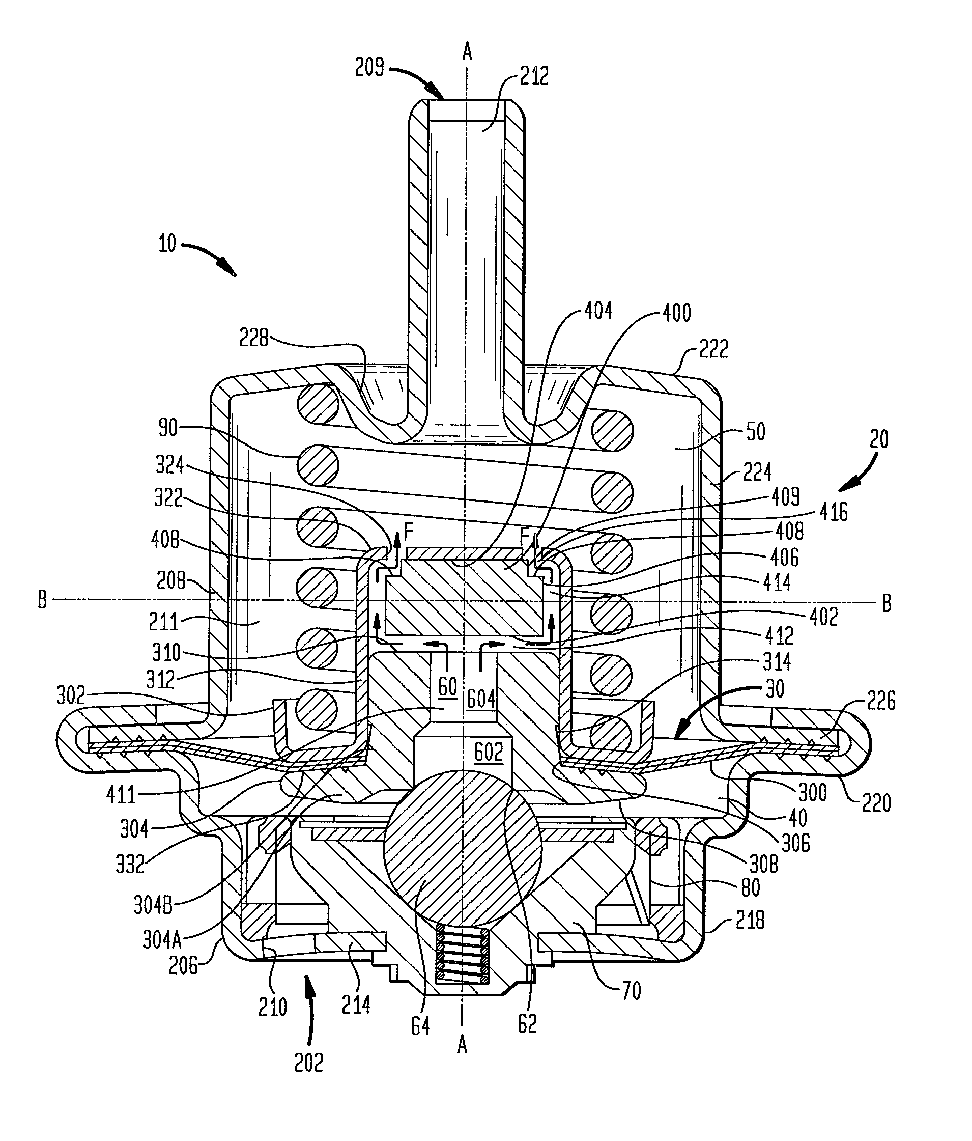
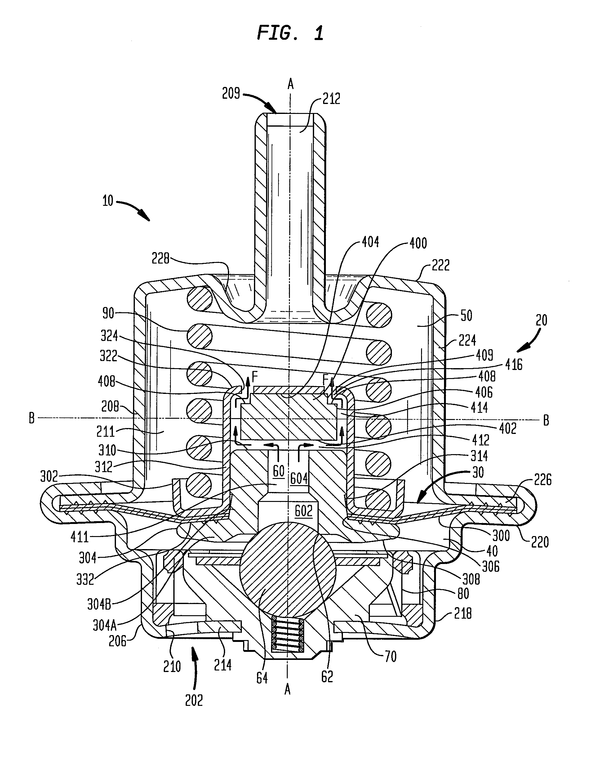
[0015]FIG. 1 illustrates a flow-through pressure regulator 10 according to a preferred embodiment. The flow-through pressure regulator 10 includes a housing 20. The housing 20 is separated by a divider 30 into a first chamber 40 and a second chamber 50. The divider 30 has a passage 60 that communicates the first chamber 40 with the second chamber 50. A closure member 70 permits or inhibits flow through the passage 60. A filter 80 may be disposed in the flow path of the housing 20. The housing 20 has an inlet 202 and an outlet 204 offset along a longitudinal axis A—A. The housing 20 can include a first housing part 206 and a second housing part 208 that are crimped together to form a unitary housing 20 with a hollow interior 211. Although the unitary housing is formed by two joined members, it is to be understood that the unitary housing could be formed with multiple members integrated together or, alternatively, a monolithic member. The inlet 202 of the housing 20 is located in the ...


PUM


Abstract

A flow-through pressure regulator having a housing, and a divider. The housing includes an inlet and an outlet disposed along a longitudinal axis. The divider separates the housing into a first chamber and a second chamber, and includes a seat, a diaphragm, a retainer and a flow distributor member. The seat includes a sealing surface and a second surface, and defines a first flow path from the sealing surface to the second surface. The diaphragm extends between the housing and the seat. The retainer secures the diaphragm to the seat, and may include a base portion proximate the seat, an intermediate portion extending along the longitudinal axis from the base portion toward the outlet, an end portion extending from the intermediate portion, and at least one aperture that permits fluid communication between the first flow path and the second chamber. The flow distributor member is disposed between the first flow path and the end portion, and defines a second flow path with the second seat surface such that the second flow path includes a second flow axis disposed radially outward from the longitudinal axis.

Description

FIELD OF THE INVENTION[0001]This invention relates to a pressure regulator for automotive fuel systems, and more particularly to a flow through pressure regulator having flow noise reduction.BACKGROUND OF THE INVENTION[0002]Most modern automotive fuel systems utilize fuel injectors to deliver fuel to the engine cylinders for combustion. The fuel injectors are mounted on a fuel rail to which fuel is supplied by a pump. The pressure at which the fuel is supplied to the fuel rail must be controlled to ensure the proper operation of the fuel injectors. Pressure is controlled using pressure regulators that control the pressure of the fuel in the system at all engine r.p.m. levels.[0003]Fuel flow rate through known pressure regulators tends to be low at high engine speed, as large quantities of fuel are consumed in the combustion process. At low engine speeds, less fuel is consumed in combustion and flow rates through the pressure regulators are high. These high fuel flow rates can produc...

Claims


Application Information

Patent Timeline
Patent Type & Authority Patents(United States)
IPC IPC(8): G05D16/02G05D16/08F16K31/12G05D16/06
CPCG05D16/0666F02M69/54Y10T137/0396Y10T137/7781Y10T137/7834
Inventor FRANCIS, KEVINKILGORE, JASON T.
Owner VITESCO TECH USA LLC
Features
  • R&D
  • Intellectual Property
  • Life Sciences
  • Materials
  • Tech Scout
  • Unparalleled Data Quality
  • Higher Quality Content
  • 60% Fewer Hallucinations
Learn More