Pulse generating apparatus and method

a pulse generator and apparatus technology, applied in the field of pulse generators, can solve the problems of difficult management of signals having respective wavelengths, inability to arbitrarily and accurately implement repetition frequency, and complex configuration of locked laser pulse light sources, etc., to achieve high duty ratio, accurate and stably operate, and control with ease

Inactive Publication Date: 2006-08-08
FUJITSU LTD
View PDF19 Cites 20 Cited by
  • Summary
  • Abstract
  • Description
  • Claims
  • Application Information

AI Technical Summary

Benefits of technology

[0018]An object of the present invention is to provide an apparatus and method generating an optical pulse of picosecond class (having a high duty ratio) that operates accurately and stably at an arbitrary repetition frequency, has a high OSNR, and is not restricted by an RF modulation frequency.
[0022]The present invention enables the generation of an optical pulse that can be controlled with ease, accurately and stably operates at an arbitrary repetition frequency, is not restricted by the frequency of a modulation signal, and has a pulse width of picosecond class with a high duty ratio.

Problems solved by technology

Therefore, it is difficult to manage signals having respective wavelengths.
Its configuration becomes very complex.
However, there is a problem that the mode-locked laser pulse light sources cannot arbitrarily and accurately implement the repetition frequency of an optical pulse due to their structures.
Its implementation is difficult if its yield in commercialization is considered.
However, since the length of the resonator is long, it significantly varies with a small temperature change, etc.
Therefore, it is difficult to stably operate the laser at an arbitrary and accurate repetition frequency.
However, since the optical transmission loss of the EAM is large, the optical signal-to-noise ratio (OSNR) of generated pulse light is significantly deteriorated when output power is amplified with an optical amplifier.
This leads to the deterioration of the OSNR.
Additionally, it is difficult to generate an optical pulse having a high ratio (duty ratio) of the cycle time of a modulation frequency to the time width of the optical pulse, since the waveform of the generated optical pulse depends on that of the RF signal source for driving the EAM.
However, it is difficult to manufacture a mode-locked laser pulse light source having an accurate length of a resonator also from a yield viewpoint, and to implement stable operations at an arbitrary and accurate repetition frequency.
However, there are disadvantages such that: (1) an optical transmission loss in an optical intensity modulator is large, leading to the deterioration of the OSNR, and (2) it is difficult to generate an optical pulse having a high duty ratio since the width of the pulse is restricted by a modulation frequency.

Method used


Image

  • Pulse generating apparatus and method
  • Pulse generating apparatus and method
  • Pulse generating apparatus and method

Examples


Embodiment Construction

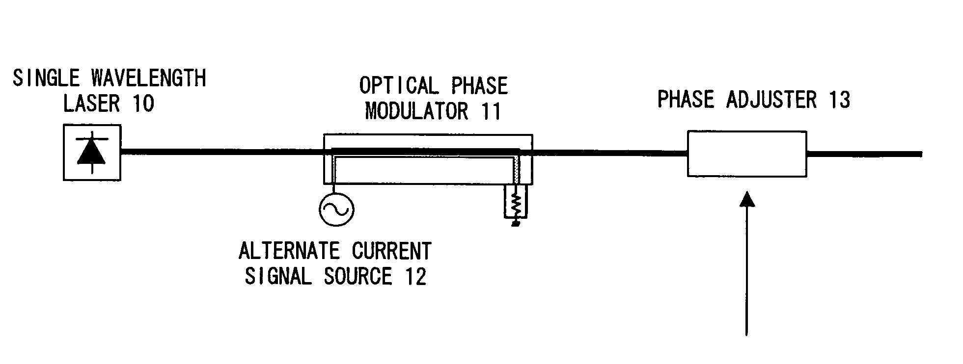
[0028]The object is achieved by the following means in a preferred embodiment according to the present invention.

[0029]Firstly, phase modulation of a frequency f0 is performed for light output from a single wavelength laser light source (frequency f). At this time, assume that ω (ω=2πf) is the angular frequency of a single wavelength laser light source, p is a modulation angular frequency (p=2πf0), m is the phase modulation index, and Jν is Bessel function of the first kind of an order ν. In this case, the real part of light generated as a result of the phase modulation is represented by an equation (2).

[0030]f⁡(t)=⁢A⁢⁢cos⁡(ω⁢⁢t+m⁢⁢cos⁡(pt))=⁢A⁢∑v=-∞∞⁢⁢Jv⁡(m)⁢cos⁡[(ω+vp)⁢t+v⁢π2](2)

[0031]This equation indicates that a new wavelength component (mode of the order ν) is generated for each modulation angular frequency ρ (namely, a frequency interval f0). Hereinafter, this component is referred to as a modulation spectrum component. Here, specific numerical values of the used frequency f ...


PUM

PropertyMeasurementUnit
repetition frequency f0aaaaaaaaaa
lengthaaaaaaaaaa
lengthaaaaaaaaaa

Abstract

An apparatus and method generating an optical pulse of picosecond class (having a high duty ratio), which accurately and stably operates at an arbitrary repetition frequency, has a high OSNR, and is not restricted by an RF modulation frequency, are provided. New modulation spectrum components are generated by performing phase modulation for light output from a single wavelength laser light source with an optical phase modulator. The phases of the modulation spectrum components are aligned by a phase adjuster, so that a pulse wave in a time domain is generated.

Description

BACKGROUND OF THE INVENTION[0001]1. Field of the Invention[0002]The present invention relates to an apparatus generating an optical pulse.[0003]2. Description of the Related Art[0004]An optical communications system currently adopts a wavelength division multiplexing (WDM) method implementing a communications bit rate of 10 giga bits / s (Gb / s, giga: 109) or 40 Gb / s. With this method, however, the number of wavelengths becomes greater with an increase in a communications capacity. Therefore, it is difficult to manage signals having respective wavelengths. Additionally, a system that synchronizes signal light beams having different wavelengths, and executes signal processing in real time is required. Its configuration becomes very complex. From such viewpoints, an optical time division multiplexing (OTDM) method that enables a mass-capacity communication is considered promising. For example, a communications light source used in the OTDM must stably generate an optical pulse that is ac...

Claims


Application Information

Patent Timeline
Patent Type & Authority Patents(United States)
IPC IPC(8): G02F1/01G02F1/03G02F1/07H03K3/42
CPCG02F1/0311G02F2203/50H04B10/508
Inventor TAKITA, YUTAKAWATANABE, SHIGEKIFUTAMI, FUMIO
Owner FUJITSU LTD
Why Eureka
Try Eureka