Generator having a plastic frame

a generator and frame technology, applied in the field of generators, can solve the problems of difficult movement of such a generator, heavy generators are very often too heavy, etc., and achieve the effect of convenient and clean method

Inactive Publication Date: 2006-08-15
PRAMAC AMERICA
View PDF9 Cites 18 Cited by
  • Summary
  • Abstract
  • Description
  • Claims
  • Application Information

AI Technical Summary

Benefits of technology

[0006]In accordance with an embodiment, a generator is provided having a plastic frame. The plastic frame provides an aesthetically pleasing outer appearance for the generator, and permits the frame to be configured as an enclosure for the generator. In accordance with an embodiment, the frame includes plastic panels surrounding the generator, providing an enclosure for the engine and alternator assembly and permitting additional features to be added to the frame without adding additional pieces. For example, an integral console may be provided on one or more of the panels. In addition to providing an enclosure, the plastic panels provide support for the engine and alternator assembly.
[0009]In accordance with another embodiment, an oil drain chute is provided in one portion of the frame. The oil drain chute extends from under the engine to outside the frame and is positioned beneath a drain plug for the engine. Removal of the oil plug allows the oil to drain into the oil drain chute and flow outside the frame, providing a clean and convenient method for changing the oil in the generator. The oil drain chute may be provided, for example, in one of the panels in the enclosure for the generator.

Problems solved by technology

To this end, the portable generators often include wheels and a handle, because generators are very often too heavy for comfortable lifting.
In fact, a typical generator weighs 200 pounds or more, so moving such a generator can be difficult if wheels are not provided.

Method used


Image

  • Generator having a plastic frame
  • Generator having a plastic frame
  • Generator having a plastic frame

Examples


Embodiment Construction

[0020]In the following description, various embodiments of the present invention will be described. For purposes of explanation, specific configurations and details are set forth in order to provide a thorough understanding of the embodiments. However, it will also be apparent to one skilled in the art that the present invention may be practiced without the specific details. Furthermore, well-known features may be omitted or simplified in order not to obscure the embodiment being described.

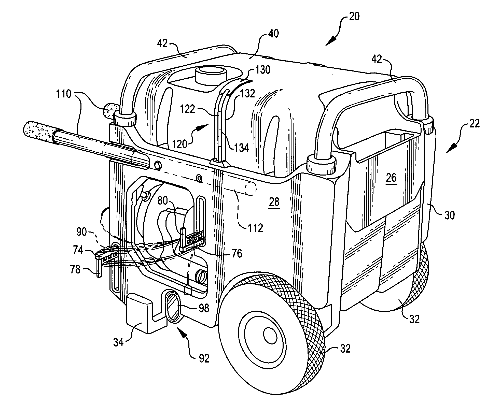
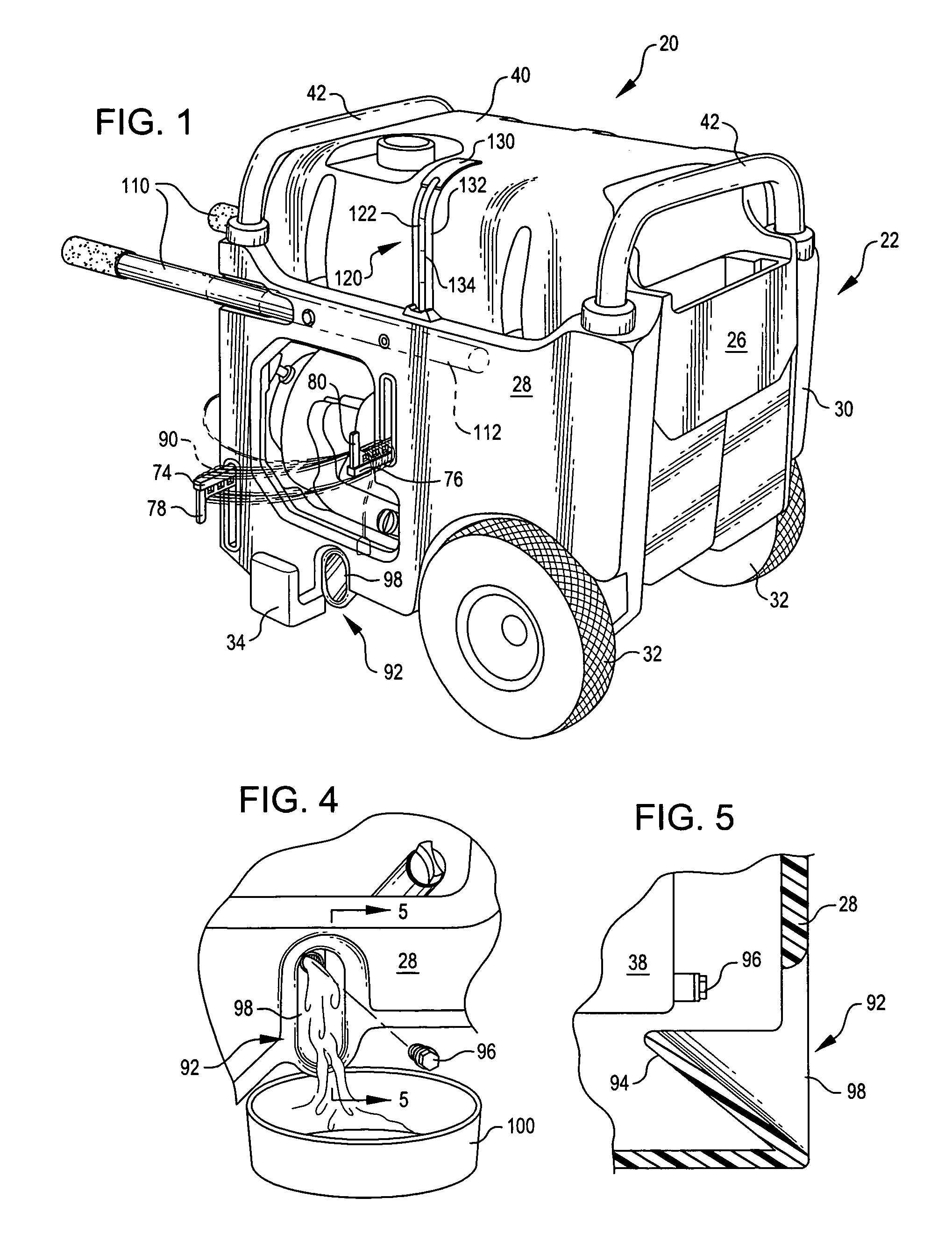
[0021]Referring now to the drawings, in which like reference numerals represent like parts throughout the several views, FIG. 1 shows a generator 20 incorporating an embodiment of the invention. Briefly described, the generator 20 includes a novel frame 22 that is formed of plastic.

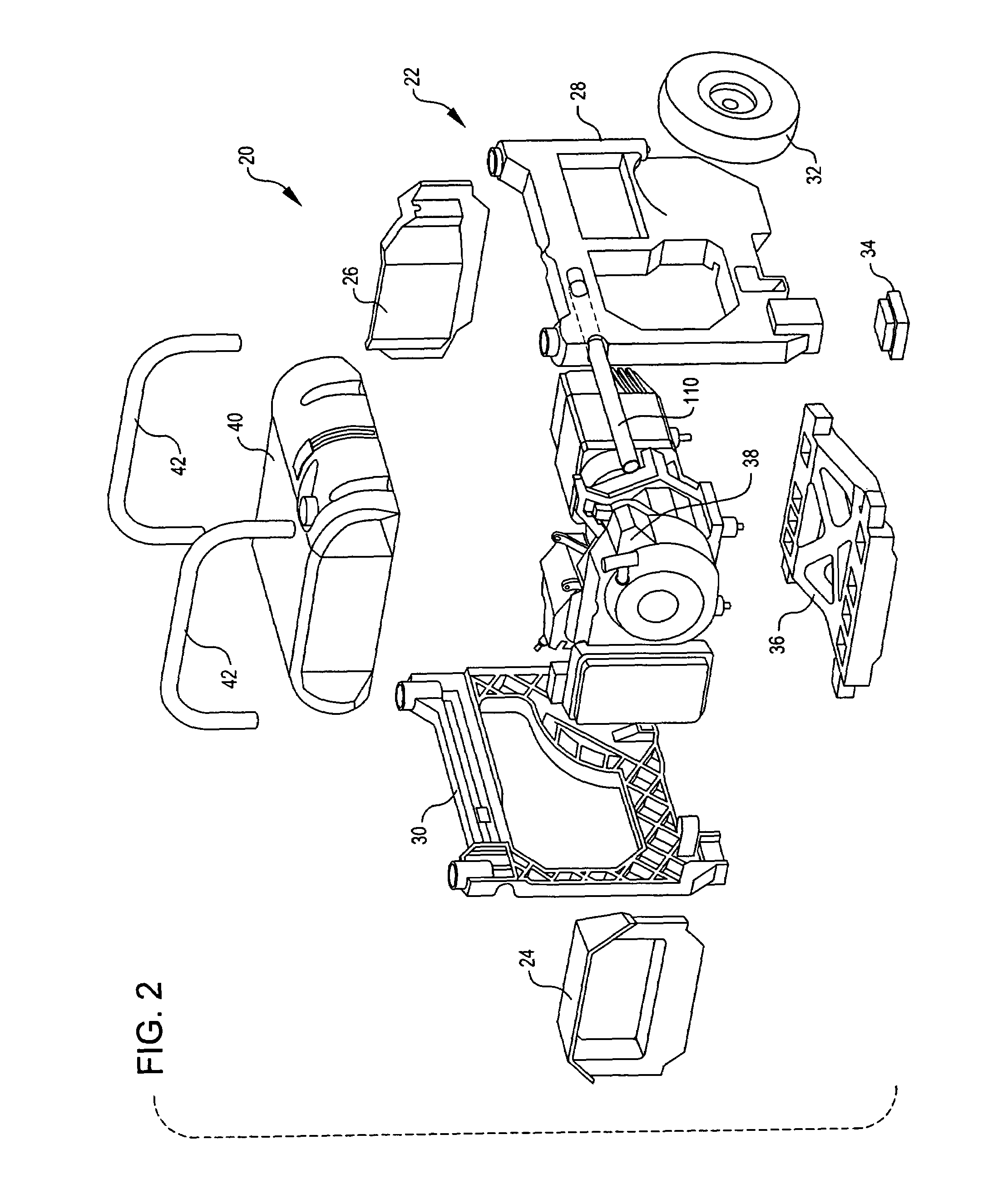
[0022]Turning now to FIG. 2, the frame 22 includes a front panel 24, a back panel 26, a right panel 28, and a left panel 30. In accordance with an embodiment, each of these panels 24, 26, 28, and 30 is connected togethe...


PUM


Abstract

A generator having a plastic frame. The frame includes plastic panels surrounding the engine and alternator assembly for the generator, providing an enclosure for the engine and alternator assembly and permitting additional features to be added to the frame without adding additional pieces. A retractable cord wrap folds into and out of recesses in one or more panels of the generator. An oil drain chute is provided in one portion of the frame. A retractable handle is extendable from a first recessed position in which the handle is substantially contained within the frame for the generator to an extended position in which the handle extends outward from the frame. A fuel gauge extends along the outer portion of a fuel tank and is formed from a translucent tube.

Description

TECHNICAL FIELD OF THE INVENTION[0001]The present invention relates generally to generators, and more particularly to portable generators.BACKGROUND OF THE INVENTION[0002]In general, a generator is a machine by which mechanical energy is changed into electrical energy. Typically, generators include an internal combustion engine that burns gasoline, diesel, or propane to produce 120 or 240 volt sine-wave power. Contemporary generators are fuel efficient, and can last for several hours on a tank of fuel.[0003]Many contemporary generators are portable so that they may be stored in one location, such as inside a garage, and moved to a second location, such as outside of buildings, for operation. To this end, the portable generators often include wheels and a handle, because generators are very often too heavy for comfortable lifting. In fact, a typical generator weighs 200 pounds or more, so moving such a generator can be difficult if wheels are not provided.[0004]In general, the design...

Claims


Application Information

Patent Timeline
Patent Type & Authority Patents(United States)
IPC IPC(8): F02B53/00F02B63/00F02B63/04H02K1/22
CPCF02B63/04F02B2063/045F02B63/047
Inventor JOHNSON, ANDREW J.ALBRIGHT, JR., JERE B.SHOKRZADEH, SAEID
Owner PRAMAC AMERICA
Why Eureka
Try Eureka