Ski exercising and training apparatus

a training apparatus and ski technology, applied in the field of ski exercise and training apparatus, can solve the problems of serious injury, dislodge a user, and inability to meet the cost and assembly requirements of the joining and spacing rails, and achieve the effect of improving the cost and assembly efficiency

Inactive Publication Date: 2006-08-15
LOANE R JOEL
View PDF15 Cites 82 Cited by
  • Summary
  • Abstract
  • Description
  • Claims
  • Application Information

AI Technical Summary

Benefits of technology

[0018]In another aspect of the invention, in a mechanism for mounting a roller between two vertical walls spaced apart by a first distance, the roller for restraining and guiding a power band for a ski exercising apparatus having a wheeled carriage rolling on partially arcuate rails, the power band affixed to the carriage and passing around a roller in the mechanism, an improved roller axle is provided, comprising a first element including an axle portion of a first diameter and a length equal to the first distance, having a concentric threaded hole on a first end, an engagement portion concentric with the axle portion, of a length equal to a thickness of one of the walls, and larger in diameter than the axle portion to match a diameter of a hole in the one of the walls, and a he

Problems solved by technology

The purpose of the safety strap is to provide for a situation in which the aforementioned flexible member might rupture on one side of the carriage, providing a sudden force urging the carriage to the side where the flexible member remains unruptured, which sudden force could dislodge a user and perhaps cause serious injury.
This particular method of joining and spacing the rails has not proved entirely satisfactory in terms of cost and ease of assembly, and in terms of strength

Method used


Image

  • Ski exercising and training apparatus
  • Ski exercising and training apparatus
  • Ski exercising and training apparatus

Examples


Embodiment Construction

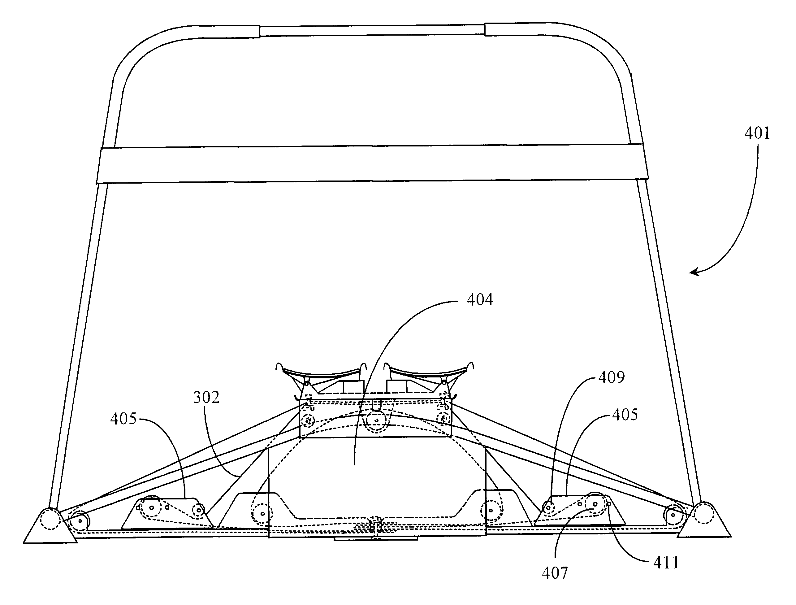
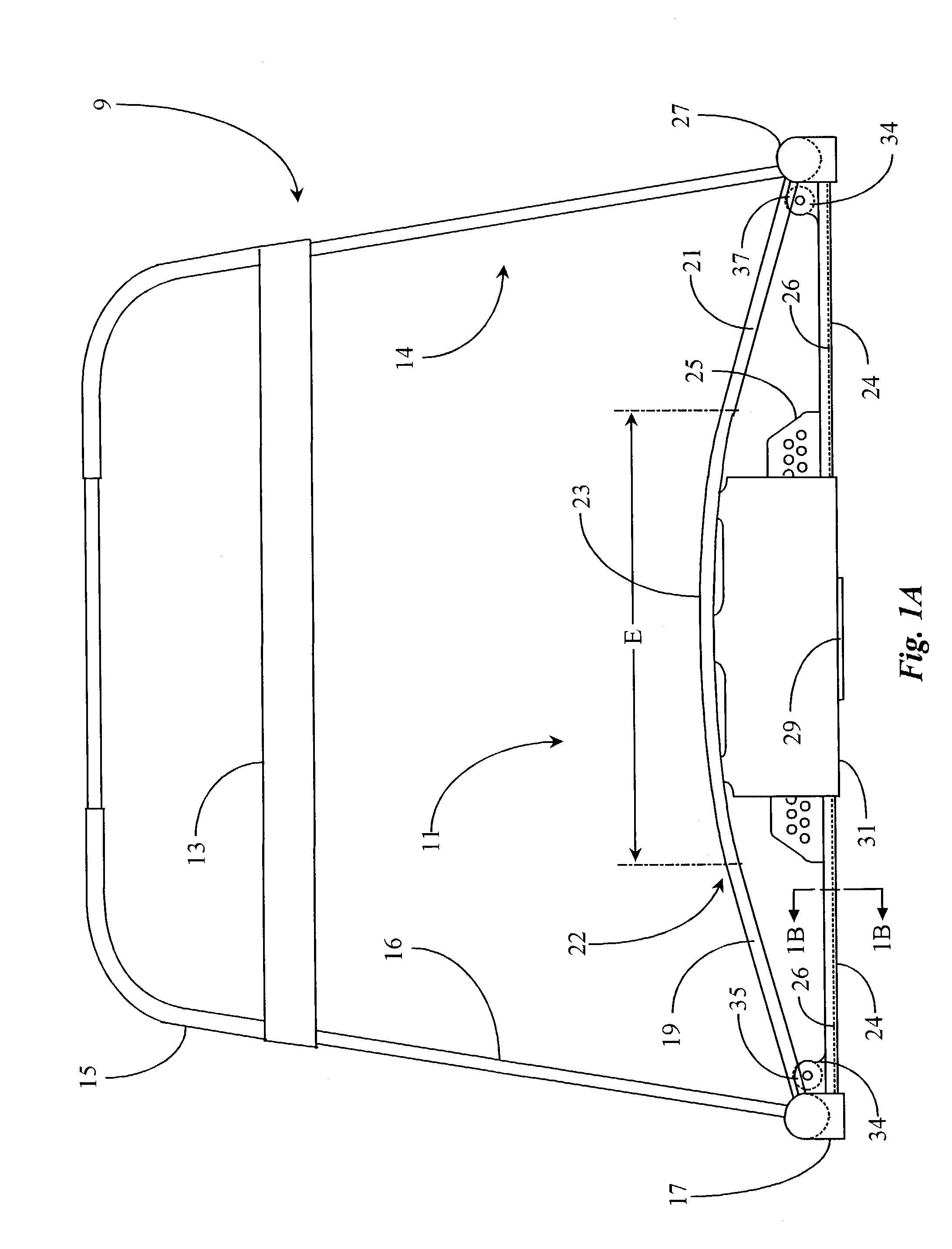
[0100]It is the object of the present invention to provide a ski exercising apparatus similar to that apparatus covered in cross-related documents above that is modularly enhanced such that, among other improvements, changing applications on the apparatus may be performed with minimal effort. It is also an object of the present invention that the above apparatus be generally and innovatively improved to accomplish a goal of maintaining a light weight while increasing strength and durability of the apparatus. A further object of the present invention is to provide such an apparatus as described above having a lower profile, improved safety features, and having fewer assembly parts with which to contend. It is also an object of the present invention to more accurately simulate the motions and dynamics of skiing in terrain, which varies in steepness, bumpiness and other aspects of the terrain, as well as skiing in such terrain at varying speeds and aggressiveness. Yet another object of...


PUM


Abstract

A ski exercising apparatus has a set of at least two parallel, partially arcuate rails joined to an underlying frame structure at opposite ends, the rails providing a track rising from each end, a wheeled carriage riding on the track, such that the carriage, in side-to-side movement rises to a maximum height at the center of the track, and descends from the center to each side, at least one articulated footpad mounted to the wheeled carriage, and at least one power band providing constraint for the wheeled carriage as it rides on the track. A variety of improvements in such an exercising apparatus are taught and claimed.

Description

CROSS-REFERENCE TO RELATED DOCUMENTS[0001]The present application claims priority as a continuation in part application of application Ser. No. 09 / 533,614, filed Mar. 22, 2000 (now U.S. Pat. No. 6,569,064 issued on May 27, 2003. The present application is also related in part to application Ser. No. 07 / 577,101, now U.S. Pat. No. 5,147,257 issued on Sep. 15, 1992 and filed on Sep. 4, 1990, which is a divisional of application Ser. No. 07 / 178,354, now U.S. Pat. No. 4,953,853 issued on Sep. 4, 1990 and filed on Apr. 6, 1988, which is a continuation-in-part of application Ser. No. 07 / 080,755, now U.S. Pat. No. 4,743,014 issued on May 10, 1988 and filed on Jul. 30, 1987. The present application is also related to U.S. Pat. No. 5,020,793 issued on Jun. 4, 1991 filed on Oct. 24, 1989, which is also a continuation-in-part of U.S. Pat. No. 4,743,014.FIELD OF THE INVENTION[0002]The present invention relates to exercising apparatus for a user to simulate the motions, exertions and techniques i...

Claims


Application Information

Patent Timeline
IPC IPC(8): A63B69/18A63B21/055A63B22/16A63B23/04A63C
CPCA63B21/0552A63B21/1415A63B21/1419A63B21/1423A63B21/154A63B22/203A63B22/205A63B69/18A63B21/00069A63B2208/0204A63B21/0442A63B22/0046A63B22/16A63B69/187A63B71/0622A63B2022/003A63B2022/0033A63B2022/0038A63B2022/185A63B2022/206A63B21/0428A63B21/4011A63B21/4009A63B21/4007
Inventor LOANE, R. JOEL
Owner LOANE R JOEL
Why Eureka
Try Eureka