Rejection of power supply variations for gain error cancellation in pulse-width-modulated motor controllers

a technology of pulse-width modulation and power supply variation, applied in the direction of maintaining head carrier alignment, recording information storage, instruments, etc., can solve the problem of lengthening the track settling tim

Active Publication Date: 2006-08-15
TEXAS INSTR INC
View PDF8 Cites 18 Cited by
  • Summary
  • Abstract
  • Description
  • Claims
  • Application Information

AI Technical Summary

Problems solved by technology

In addition, some conventional disk drive systems do not use electrical feedback for control of the position of the data transducers, and thus for control of the voice coil motor, but instead use a mechanical positioning device for such control.
It is believed that these gain variations will lengthen the track settling times, and in severe cases may cause positioning errors.

Method used


Image

  • Rejection of power supply variations for gain error cancellation in pulse-width-modulated motor controllers
  • Rejection of power supply variations for gain error cancellation in pulse-width-modulated motor controllers
  • Rejection of power supply variations for gain error cancellation in pulse-width-modulated motor controllers

Examples


Embodiment Construction

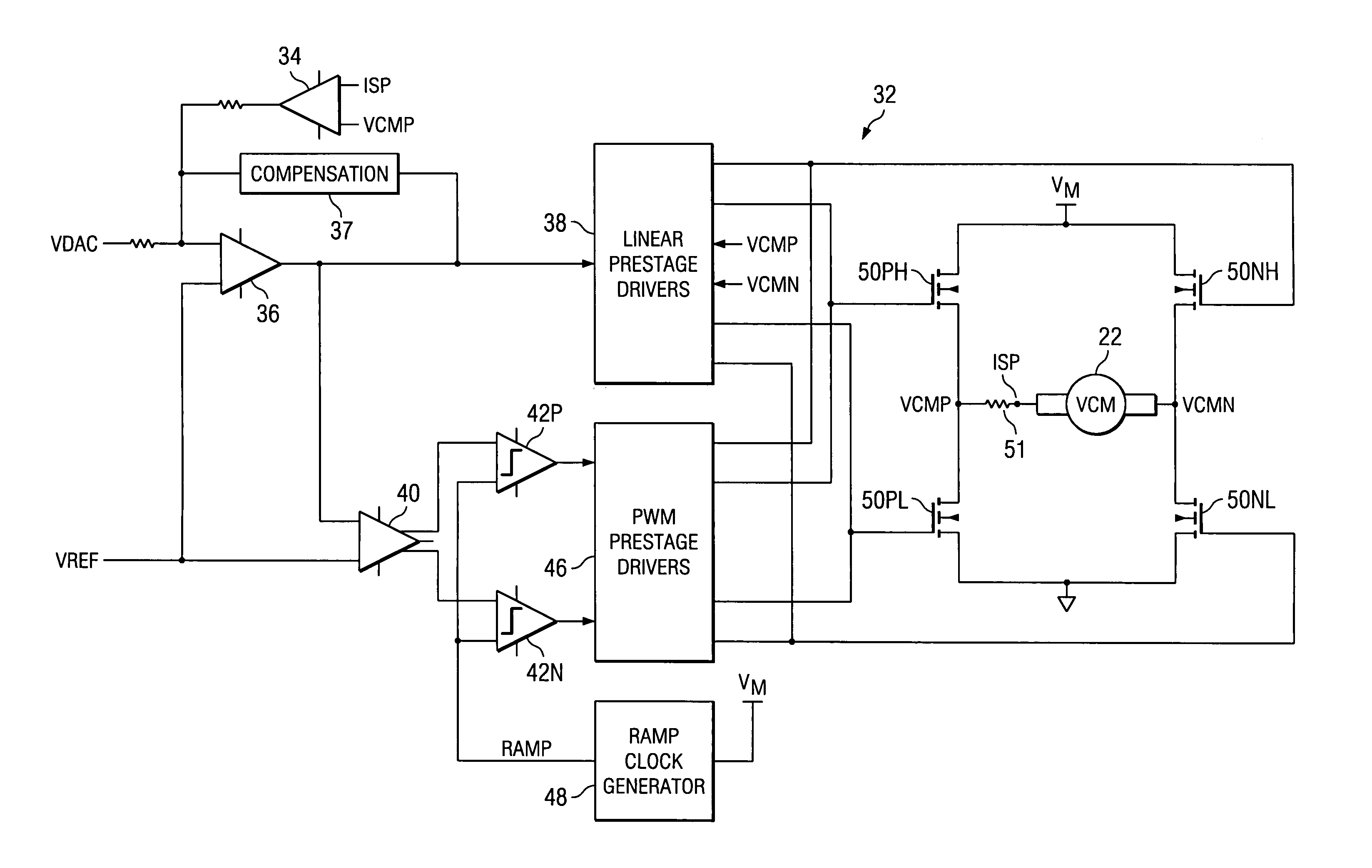
[0030]The present invention will be described in connection with its preferred embodiment, namely as implemented into a drive circuit for a voice coil motor in a modem computer disk drive system, because the advantages provided by this invention are contemplated to be especially beneficial in such an application. However, it is also contemplated that this invention may be used to advantage in other applications, and that such uses will be apparent to those skilled in the art having reference to this specification. Accordingly, it is to be understood that the following description is provided by way of example only, and is not intended to limit the true scope of this invention as claimed.

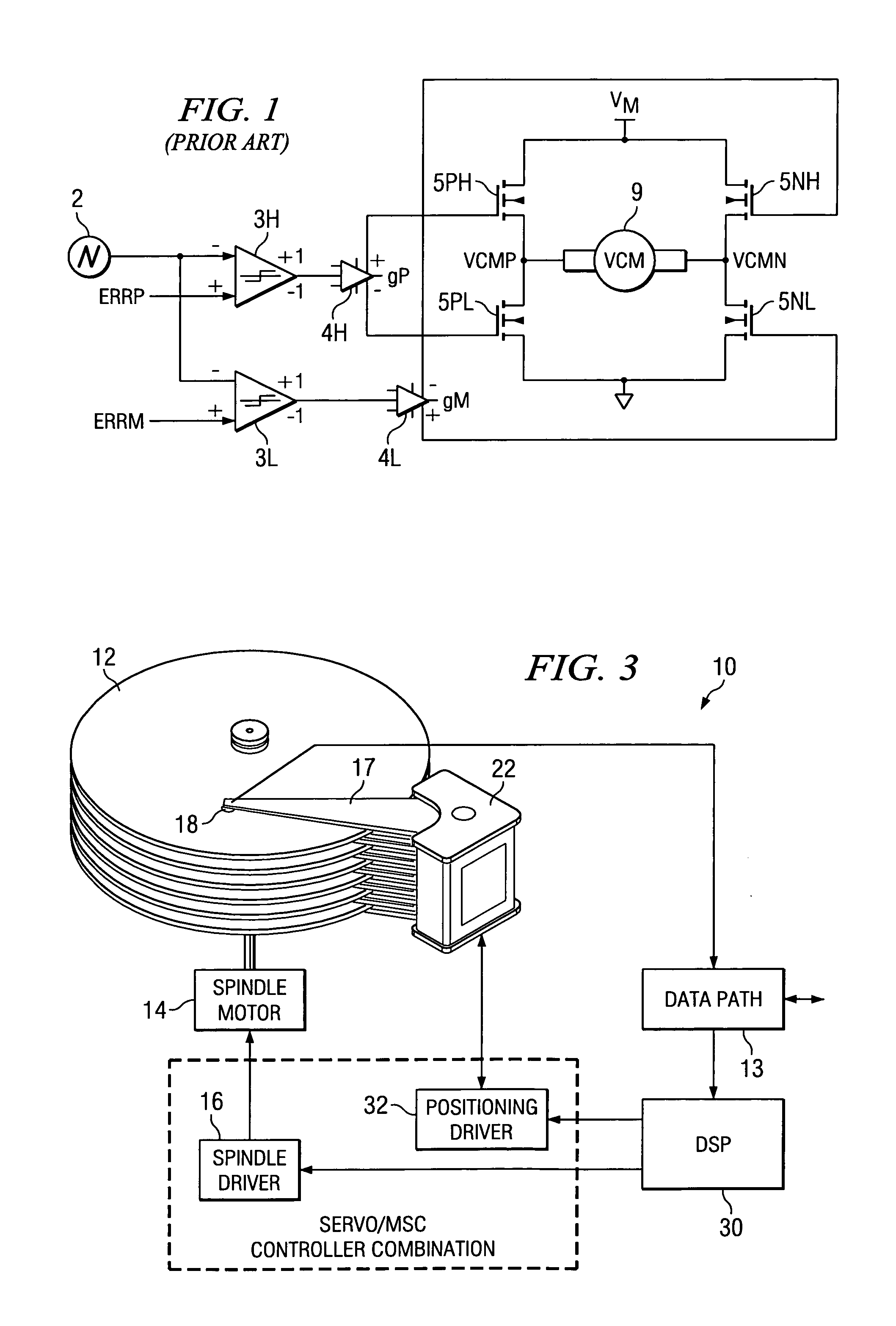
[0031]FIG. 3 generically illustrates disk drive system 10 constructed according to the preferred embodiment of the invention. Disk drive system 10 includes one or more magnetic media disks 12 that are rotated by spindle motor 14 in response to spindle driver circuit 16. Data transducer 18 is the read...


PUM

PropertyMeasurementUnit
voltage VMaaaaaaaaaa
peak-to-peak voltageaaaaaaaaaa
voltage VMaaaaaaaaaa

Abstract

A positioning driver (32) for a voice coil motor (22) in a disk drive system (10) is disclosed. Pulse-width-modulated prestage drivers (46) are coupled to power transistors (50) arranged in an “H” bridge for driving the voice coil motor (22), biased with a power supply voltage (VM). The pulse-width-modulated prestage drivers (46) drive the power transistors (50) according to a comparison between an error signal from an error amplifier (36) and a ramp clock signal (RMP) generated by a ramp clock generator (46). The ramp clock generator (46) includes a control circuit (68) that modulates the high and low limits of the ramp clock signal (RMP) in response to variations in the power supply voltage (VM). This modulation of the high and low limits compensates for variations in the gain of the power transistors (50) resulting from variations in the power supply voltage (VM). The control circuit (68) may also modulate the slope of the ramp clock signal (RMP) according to variations in the power supply voltage (VM), for example to maintain a constant frequency.

Description

CROSS-REFERENCE TO RELATED APPLICATIONS[0001]This application claims priority, under 35 U.S.C. §119(e), of Provisional Application No. 60 / 575,457, filed May 28, 2004.STATEMENT REGARDING FEDERALLY SPONSORED RESEARCH OR DEVELOPMENT[0002]Not applicable.BACKGROUND OF THE INVENTION[0003]This invention is in the field of motor control, and is more specifically directed to control of voice coil motors as used in computer disk drive controllers.[0004]As is evident in the industry, the magnetic disk drive remains the dominant technology for mass read / write storage in modem computers, including both desktop workstations and also portable “laptop” computers. Magnetic disk drives are now also popular in smaller scale portable systems, such as portable audio systems and players.[0005]Modern disk drives typically include a “spindle” motor and a “voice coil” motor. The spindle motor spins the magnetic disks during operation, so that sectors at a given radius of the disk pass by the data transducer...

Claims


Application Information

Patent Timeline
Patent Type & Authority Patents(United States)
IPC IPC(8): G11B21/02G11B5/55G11B5/596
CPCG11B5/556G11B5/022H02M7/5395H02P27/085H02P31/00H02P2209/09H02P25/034H02M1/0022H02M1/0025
Inventor EL-SHERIF, ALAA Y.PLUTOWSKI, EUGENE F.ZIEMER, KEVIN W.
Owner TEXAS INSTR INC
Why Eureka
Try Eureka