System and method for post filtering peak power reduction in multi-carrier communications systems

Active Publication Date: 2006-08-22
INTEL CORP
View PDF44 Cites 30 Cited by
  • Summary
  • Abstract
  • Description
  • Claims
  • Application Information

AI Technical Summary

Benefits of technology

[0040]A number of different embodiments of the present invention have been described in relation to the various figures. Nonetheless, it will be appreciated by those skilled in the art that a variety of additional embodiments are possible within the teachings of the present invention. For example, a variety of specific peak reduction correction calculation circuits implementing specific algorithms may be provided, a variety of different correction filter implementations and band pass characteristics may be provided, and a variety of different gain weighting embodiments may be provided, all employing the teachings of the present invention and limitations of space prevent an exhaustive list of all the possible circuit implementations or an enumeration of all possible algorithms. A variety of other possible modifications and additional embodiments are also clearly possible and fall within the scope of the present invention. Accordingly, the described specific embodiments and implementations should not be viewed as in any sense limiting in nature and are merely illustrative of the present invention.

Problems solved by technology

These communication systems are being placed under increasing performance demands that are taxing the capability of available equipment, especially wireless base station equipment.
The increasing number of wireless users is of course readily apparent and this trend is unlikely to slow due to the convenience of wireless services.
Increased carrier bandwidth may cause operation outside government allocated operating bands in violation of the law.
Furthermore, the filtering operation may limit plural of the peak reduction correction signals to frequency bands each corresponding to plural adjacent bands of the multi-carrier input signal.

Method used


Image

  • System and method for post filtering peak power reduction in multi-carrier communications systems
  • System and method for post filtering peak power reduction in multi-carrier communications systems
  • System and method for post filtering peak power reduction in multi-carrier communications systems

Examples


Embodiment Construction

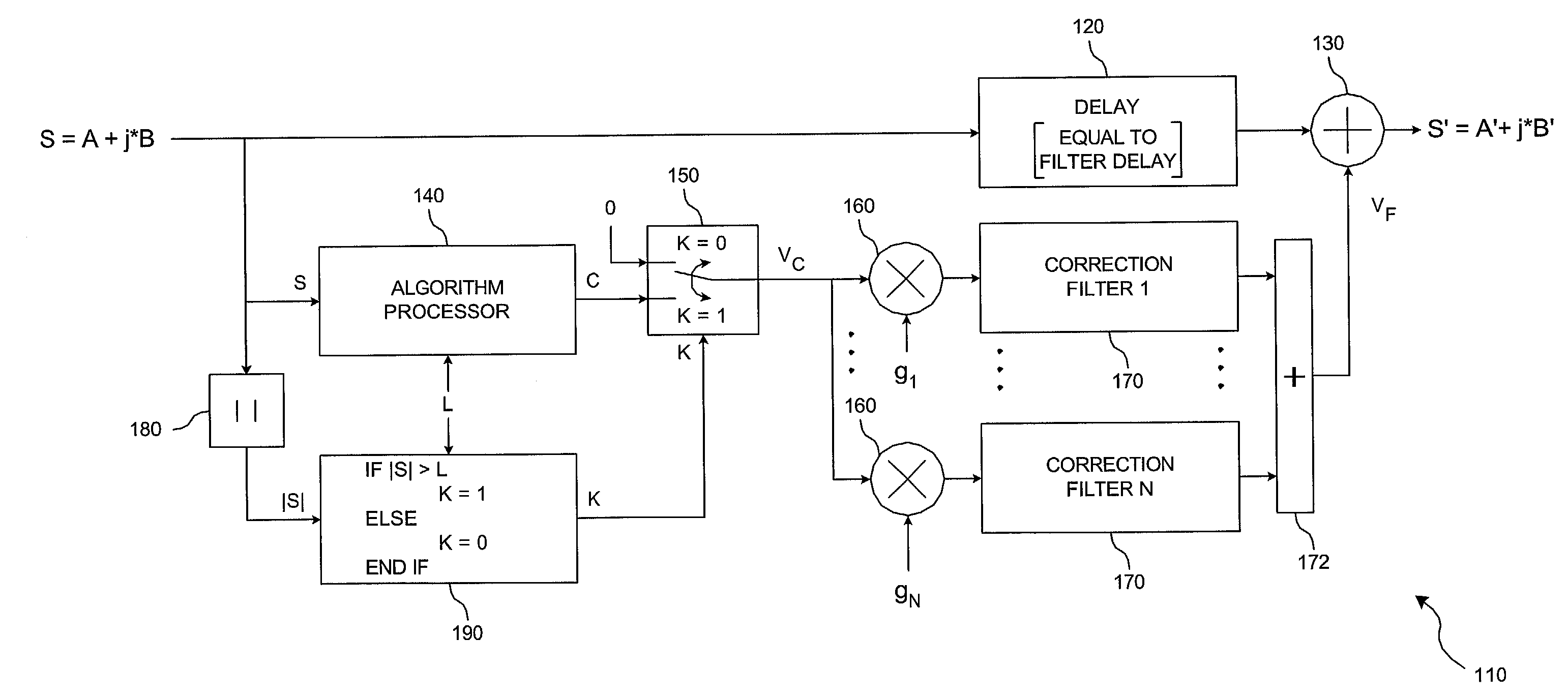
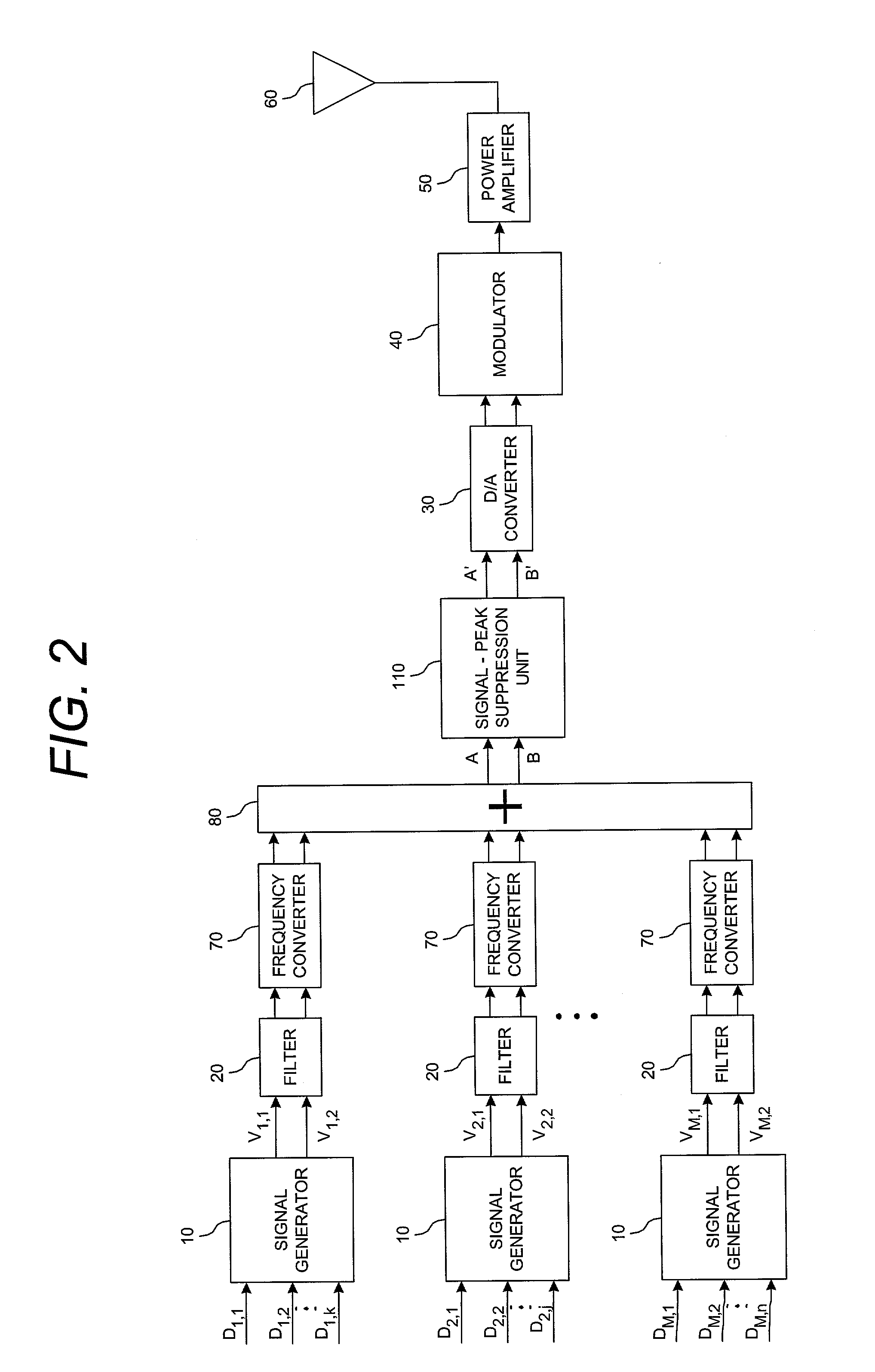
[0022]Referring to FIG. 2, a preferred embodiment of a multiple carrier communication system employing signal-peak suppression in accordance with the present invention is illustrated. A digitally sampled signal stream represented by an in-phase component stream A and a quadrature-phase component stream B is input to a signal-peak suppression unit 110. This digitally sampled signal stream represents plural transmit carriers with each of these transmit carriers providing one or more communication channels as produced by the signal generators 10, filters 20, frequency converters 70 and combiner 80. The individual carriers may comprise voice or data communication signals and for a given system all the carriers may be voice, all the carriers may be data or some of the carriers voice and some data. The signal-peak suppression unit outputs a peak-reduced signal stream represented by an in-phase component signal stream A′ and a quadrature component signal stream B′. This peak-reduced signal...


PUM


Abstract

A system and method for post filtering signal peak reduction adapted for use in a multi-carrier communication system incorporating a source of a multi-carrier communication signal band limited in plural bands corresponding to the plural carriers. A first signal path receives as an input the band limited multi-carrier communication signal. A second parallel signal path includes a peak reduction calculation circuit for calculating a peak reduction correction signal and a plurality of filters providing a plurality of parallel filtering operations on the peak reduction correction signal corresponding to the plural bands to which the communication system is limited. The filtered peak reduction correction signals and delayed input signal are combined to provide peak adjusted output signals without violating the band limits of the communication signal or the modulation scheme of the communication signal.

Description

RELATED APPLICATION INFORMATION[0001]The present application claims priority under 35 USC §119(e) of provisional application Ser. No. 60 / 309,571 filed Aug. 2, 2001, the disclosure of which is incorporated herein by reference in its entirety.BACKGROUND OF THE INVENTION[0002]1. Field of the Invention[0003]The present invention relates to communications systems that transmit signals that may be composed of plural combined transmit carriers. Each of these carriers may include one or more communication channels. More particularly, the present invention relates to wireless communications systems and signal processing apparatus employed in wireless communications systems. The term ‘wireless communications systems’ includes cellular communication systems, personal communication systems (PCS), wireless local loop systems, and all other like systems.[0004]2. Background of the Prior Art and Related Information[0005]Wireless communications systems employing transmission between base stations an...

Claims


Application Information

Patent Timeline
IPC IPC(8): H04L25/03H03C3/02H04B1/7097H04L27/26
CPCH04L27/2614H04B1/7097
Inventor HUNTON, MATTHEW J.
Owner INTEL CORP
Why Eureka
Try Eureka