High-selectivity electromagnetic bandgap device and antenna system

a high-selectivity electromagnetic and bandgap technology, applied in the direction of antennas, antenna feed intermediates, electrical devices, etc., can solve the problems of limiting the bandwidth of an antenna, tunable antennas that do not provide system selectivity, and designing such a structure can become quite difficult for low frequency applications, so as to improve the overall frequency agility of the antenna system, the effect of adding tunability to the ebg

Active Publication Date: 2006-05-09
PENN STATE RES FOUND
View PDF10 Cites 46 Cited by
  • Summary
  • Abstract
  • Description
  • Claims
  • Application Information

AI Technical Summary

Benefits of technology

[0007]Thus, problems remain with the use of EBG AMC structures and particularly to the low frequency application of EBG AMC surfaces as well as with frequency tunable antennas generally. Therefore, it is a primary object, feature, or advantage of the present invention to improve upon the state of the art.
[0008]It is a further object, feature, or advantage of the present invention to enable creation of an antenna system possessing generally narrow bandwidths such that the antenna system will screen out adjacent signals thereby providing radio system selectivity.
[0009]Yet another object, feature, or advantage of the present invention is to add tunability to an EBG to give overall antenna system frequency agility.
[0010]A still further object, feature, or advantage of the present invention is to create an ultra-thin EBG AMC structure with a high-k substrate material that operates effectively well below 1 GHz.
[0011]A still further object, feature, or advantage of the present invention is to use an ultra-thin EBG AMC structure with a high-k substrate material that operates effectively well below 1 GHz as the basis for creating a low-profile tunable narrowband (i.e., channel selective) antenna system.
[0012]Yet another object of the present invention is that it provides for limiting the bandwidth of an antenna such that it allows only one channel or a select group of adjacent channels through the antenna at any one time such that the antenna can be said to be narrowband and frequency selective with the antenna system adding frequency selectivity to an overall receiver system.

Problems solved by technology

Frequency tunable antennas are known to exist but such antennas do not provide a narrow bandwidth of operation.
Moreover such frequency tunable antennas do not provide for system selectivity.
However, designing such a structure can become quite challenging for low frequency applications, specifically below 1 GHz.
This is mainly because the substrate dimensions needed to achieve reasonable bandwidths of at least 5% or more are much too thick for most practical purposes.
Thus, problems remain with the use of EBG AMC structures and particularly to the low frequency application of EBG AMC surfaces as well as with frequency tunable antennas generally.

Method used


Image

  • High-selectivity electromagnetic bandgap device and antenna system
  • High-selectivity electromagnetic bandgap device and antenna system
  • High-selectivity electromagnetic bandgap device and antenna system

Examples


Embodiment Construction

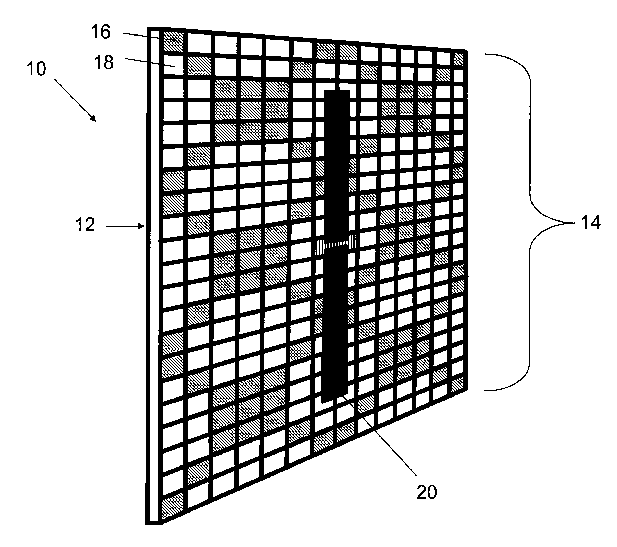
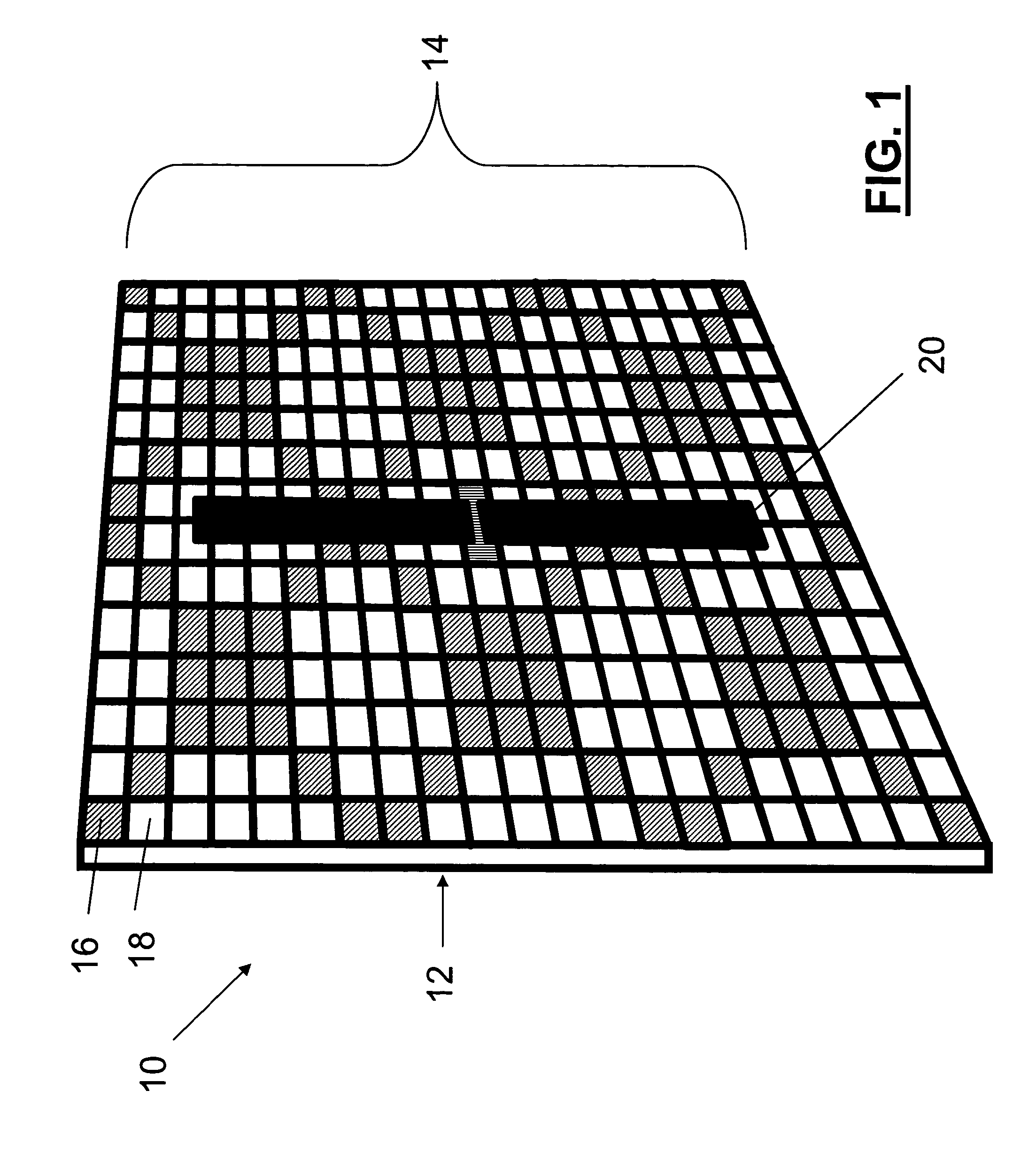
[0027]EBG materials display a reflection phase versus frequency such as that illustrated in FIG. 4. The center frequency of operation is defined as that frequency where the reflection phase is zero. This point on the frequency response curve is very unique. A consequence of zero-phase reflection is that the electric field is not flipped in polarity as is the case for all other electrical conductors (which may be considered perfect electrical conductors (PECs)), but is in fact reflected without a phase shift. This is a unique property that is provided by the operation of these resonant surfaces. In practice, the bandwidth of operation is defined as the frequency range where the reflection phase is between −90 degrees and 90 degrees.

[0028]With this unique property, antennas can be placed proximate (on or near) these surfaces without experiencing the short-circuiting effects associated with PEC ground planes. As the operating frequency with which the antenna is being driven leaves the ...


PUM


Abstract

An antenna system includes an antenna element and an electromagnetic bandgap element proximate the antenna element wherein the electromagnetic bandgap element is optimized for narrow bandwidth operation thereby providing radiofrequency selectivity to the antenna system. Preferably the electromagnetic bandgap element is tunable such as through use of a bias-alterable dielectric substrate or other tuning mechanism. The design approach also provides a means of creating an ultra-thin low-profile narrowband tunable channel selective antenna system suitable for low frequency applications.

Description

PRIORITY STATEMENT[0001]This application is a conversion of and claims priority to U.S. Provisional Patent Application No. 60 / 491,922, filed on Aug. 1, 2003, herein incorporated by reference in its entirety.GRANT REFERENCE[0002]Work for this invention was funded by grants from the Department of Defense Advanced Research Projects Agency Contract No. NBCHC010061. The United States government may have certain rights in this invention.BACKGROUND OF THE INVENTION[0003]The present invention addresses problems in several areas which are seemingly unrelated without having the benefit of the disclosure concerning the present invention. A first area of the disclosure is the general area of frequency tunable antennas. Frequency tunable antennas are known to exist but such antennas do not provide a narrow bandwidth of operation. Moreover such frequency tunable antennas do not provide for system selectivity.[0004]In typical communication systems, many communications channels are present. Each ch...

Claims


Application Information

Patent Timeline
Patent Type & Authority Patents(United States)
IPC IPC(8): H01Q15/02H01Q
CPCH01Q9/16H01Q9/28H01Q15/006H01Q15/0066H01Q15/148
Inventor WERNER, DOUGLAS H.WERNER, PINGJUAN L.WILHELM, MICHAEL J.
Owner PENN STATE RES FOUND
Why Eureka
Try Eureka