
Integrated optical filters utilizing resonators

a filter structure and resonator technology, applied in the field of optical filters, can solve the problems of large radiation loss, high loss per roundtrip, and high loss of insertion loss of such a filter structure, and achieve the effect of reducing bandwidth and insertion loss

Inactive Publication Date: 2006-06-20
LAMBDA CROSSING
View PDF13 Cites 47 Cited by
  • Summary
  • Abstract
  • Description
  • Claims
  • Application Information

AI Technical Summary

Benefits of technology

[0008]There is accordingly a need in the art to facilitate filtering of one or more optical channels from a multi-channel light signal by providing a novel resonator based filter method and structure that provides for simultaneously achieving narrow bandwidth and low insertion loss of the filtering process.
[0012]The implementation of the filter structure with several resonators also improves the out of hand rejection ratio of the structure, which deteriorates for large coupling levels.
[0021]According to yet another broad aspect of the present invention, there is provided a method for reducing a bandwidth and insertion loss while filtering at least one optical channel from a multi-channel light signal, the method comprising inputting the light signal into an input waveguide of an optical filter structure that comprises at least one closed loop resonator optically coupled to said input waveguide and at least one output waveguide with a level of the coupling from the waveguides to the resonator being at least 5 times greater than a loss-per-revolution of the resonator.
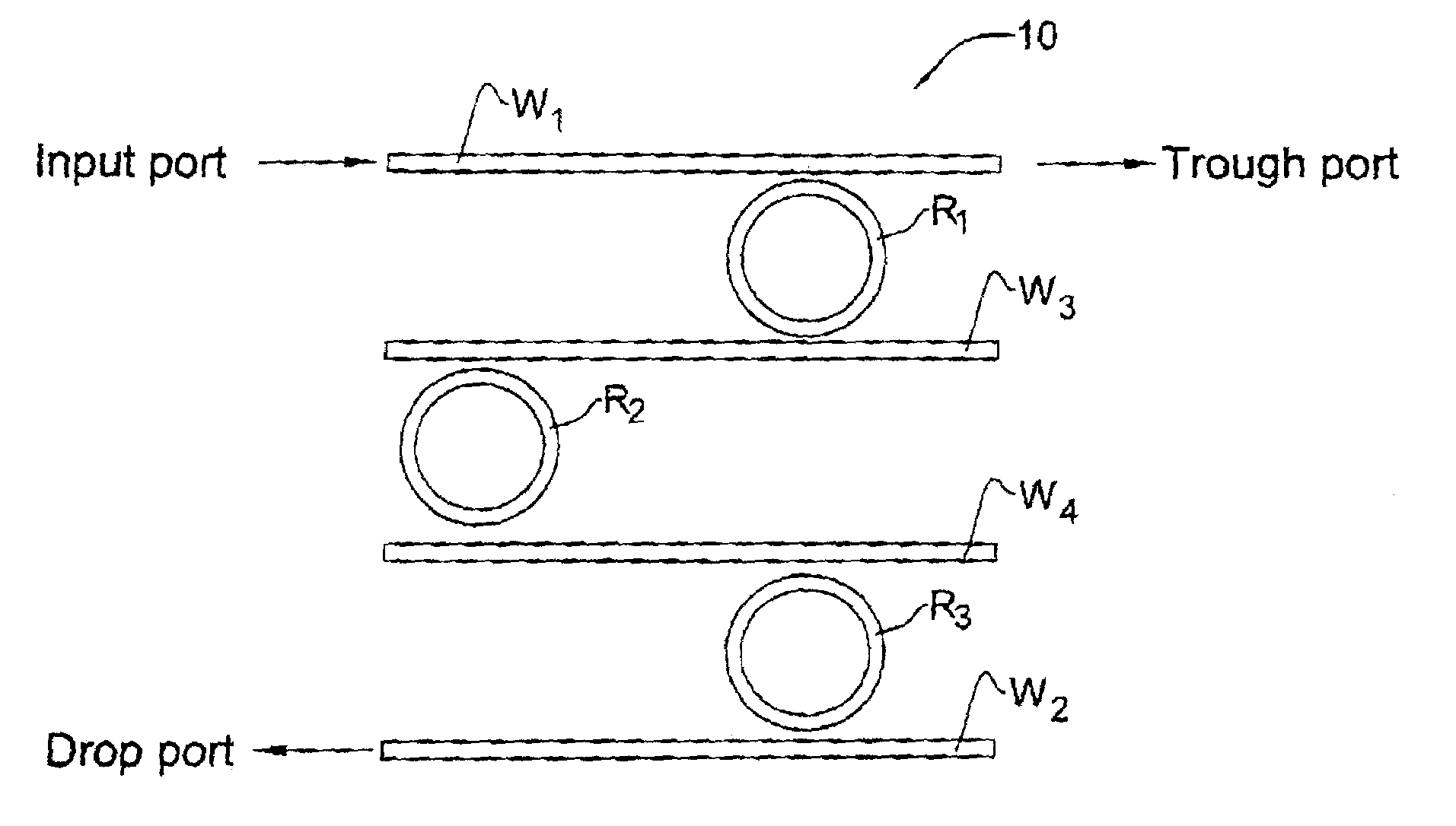
[0022]The present invention according to its yet another aspect provides a method for reducing a bandwidth and insertion loss while filtering at least one optical channel from a multi-channel light signal, the method comprising inputting the light signal into an input waveguide of an optical filter structure that comprises at least two closed loop resonators optically coupled to said input waveguide and at least one output waveguide and to each other, a level of the coupling from the waveguides to the resonator being at least 5 times greater than a loss-per-revolution of the resonator.

Problems solved by technology

For a ring or closed loop resonator, a small roundtrip requires a small curvature of the resonator, which in turn introduces large radiation losses and, hence, high loss per roundtrip.
Accordingly, the insertion loss of such a filter structure would be high due to both the inherent high loss of the resonator and the required small coupling.

Method used


Image

  • Integrated optical filters utilizing resonators
  • Integrated optical filters utilizing resonators
  • Integrated optical filters utilizing resonators

Examples


Embodiment Construction

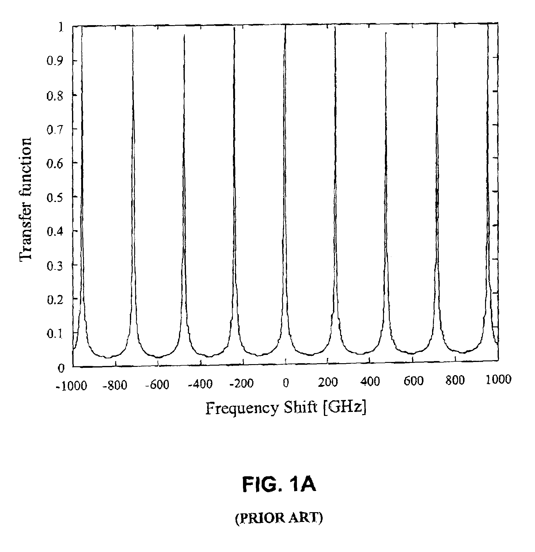
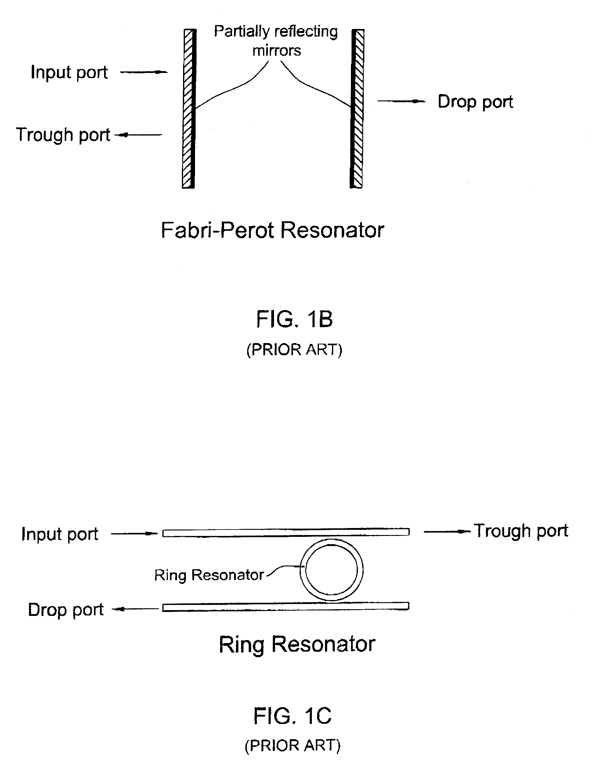
[0038]FIG. 1A illustrates the spectral response of a filter structure utilizing a resonator coupled to an input and output ports. FIG. 1B exemplifies the implementation of the resonator-based filter structure utilizing a Fabry-Perot resonator comprised of a pair of partially reflecting mirrors. FIG. 1C illustrates a filter structure utilizing a single closed-loop resonator coupled to two waveguides which serve as input / output ports.

[0039]As indicated above, a reasonable narrow bandwidth filter for DWDM communication systems requires out of band rejection ratio of at least 30 dB, minimal insertion loss and an appropriate bandwidth. These parameters depend on the architecture of the filter structure.

[0040]Turning back to FIG. 1C, this filter structure can be configured in accordance with the principles of the present invention, namely, the closed loop resonator can be selected with a relatively small FSR (but not less than the spectral band in which the filter is operating), and the c...


PUM


Abstract

A filtering method and optical filter structure are presented. The structure comprises an input waveguide, an output waveguide, and a filter stage formed by at least one closed loop resonator optically coupled to the input and output waveguides. A level of the coupling from each of the waveguides to the resonator is at least 5 times greater than a loss-per-revolution of the resonator. The filter structure thus provides for reducing a bandwidth and insertion loss while filtering at least one optical channel from a multi-channel light signal.

Description

FIELD OF THE INVENTION[0001]The present invention is generally in the field of optical devices and relates to a filtering device and method, utilizing optical resonators.BACKGROUND OF THE INVENTION[0002]Optical filters play an important role in wavelength division multiplexing (WDM) communication systems. WDM systems achieve high bandwidth transmission by combining multiple optical channels, each of a different wavelength range, in an optical fiber. A filter is utilized to extract a specific optical channel from a multi-channel signal at a receiver side, and can be either fixed to a given wavelength range or tunable across a range of wavelengths.[0003]Integrated optics provides for a compact method to realize an optical filter, and especially a tunable optical filter. One method of realizing filters in integrated optics technology is to combine multiple optical resonators [B. E. Little et al, “Microning Resonator Channel Dropping Filters”, IEEE J. Lightwave Tech. 15, 998–1005 (1997)...

Claims


Application Information

Patent Timeline
IPC IPC(8): G02B6/26G02B6/293G02B6/12G02B6/34
CPCG02B6/12007G02B6/29343G02B2006/12109
Inventor SCHEUER, JACOBMARGALIT, MOTIBORTMAN-ARBIV, DAPHNA
Owner LAMBDA CROSSING
Learn More