System for optically transmitting frequency-division-multiplexed signal and transmitter therefor

a frequency-division multiplexing and optical transmission technology, applied in the field of optical transmission systems, can solve the problems of chromatic dispersion of optical signals such as wide optical frequency spectrum, difficult to sufficiently suppress group delay variations in the band, and linear distortion that tends to occur under, so as to reduce phase noise in the fm modulated signal

Inactive Publication Date: 2007-08-21
PANASONIC CORP
View PDF11 Cites 51 Cited by
  • Summary
  • Abstract
  • Description
  • Claims
  • Application Information

AI Technical Summary

Benefits of technology

[0015]As described above, in the first aspect, the FM modulated signal is obtained through frequency modulation using a frequency-division-multiplexed signal as an original signal. The FM modulated signal is converted into an optical-intensity-modulated signal at the transmitting end. The optical-intensity-modulated signal has an optical frequency spectrum in which upper and lower sidebands distribute geometrically similarly to the frequency spectrum of the original signal for the optical modulation and in which an optical carrier component is suppressed. Then, the optical-intensity-modulated signal is photodetected based on a square-law detection characteristic at the receiving end. At the receiving end, the optical transmission system thus obtains an FM modulated signal, having a frequency deviation twice as large as the one of the original FM modulated signal produced at the transmitting end, as a received FM modulated signal. In this manner, the optical transmission system can narrow (reduce in half) the bandwidth of the FM modulated signal at the transmitting end while securing the frequency deviation thereof large enough to acquire a sufficient FM gain in FM demodulation. As a result, it is possible to prevent the waveform of the transmitted signal from being deteriorated due to the group delay characteristic of the electrical transmission line and the chromatic-dispersion of the optical transmission line, and to realize signal transmission of good quality.
[0017]As stated above, in the second aspect, the optical modulator used herein is an external optical modulator having the Mach-Zehnder interferometer structure. A modulating signal (an FM modulated signal) is applied to the optical modulator with respect to the “valley” where the output optical power is at the minimum in the input-voltage vs. output-optical-power characteristic (which is periodic like a sine wave) of the optical modulator. The optical modulator thus produces an optical-intensity-modulated signal whose optical carrier component is suppressed. The suppression of the optical carrier component prevents the waveform from being deteriorated by the chromatic-dispersion of the optical transmission line. In addition, the optical-intensity-modulated signal has an optical frequency spectrum in which upper and lower sidebands distribute geometrically similarly to the frequency spectrum of the original signal for the optical modulation. Therefore, after the optical-intensity-modulated signal is square-law detected at the receiving end, the freqeucy deviation of the FM modulated signal is doubled, thereby making it possible to realize high-quality signal transmission.
[0019]As described above, in the third aspect, the optical transmission system previously produces in the FM modulator an FM modulated signal having a frequency deviation larger enough to acquire a desired FM gain. The optical transmission system then converts the FM modulated signal into a frequency-divided FM modulated signal, and next converts the frequency-divided FM modulated signal into an optical-intensity-modulated signal for transmission. This reduces the phase noise in the FM modulated signal to be optically transmitted and FM demodulated. As a result, high-quality signal transmission can be realized.
[0021]As described above, in the fifth aspect, the optical-intensity-modulated signal produced by the optical modulator is combined with the second unmodulated light set in an opposite phase to the optical carrier component of the optical-intensity-modulated signal. The optical carrier component of the optical-intensity-modulated signal is thus canceled by the second unmodulated light. As a result, it is possible to produce an optical-intensity-modulated signal whose optical carrier component is suppressed.
[0023]As stated above, in the sixth aspect, as in the third aspect, the optical transmission system previously produces in the FM modulator an FM modulated signal having a frequency deviation larger enough to acquire a desired FM gain, then converts the FM modulated signal into a frequency-divided FM modulated signal, and converts the signal into an optical-intensity-modulated signal for transmission. It is therefore possible to reduce the phase noise in the FM modulated signal to be optically transmitted and FM demodulated.
[0025]As described above, in the seventh aspect, the optical transmission system previously produces in the FM modulator an FM modulated signal having a frequency deviation larger enough to acquire a desired FM gain, then converts the FM modulated signal into a frequency-divided FM modulated signal, and next converts the signal into an optical-intensity-modulated signal for transmission. It is therefore possible to reduce the phase noise in the FM modulated signal to be optically transmitted and FM demodulated.

Problems solved by technology

In addition, in the FM modulation scheme, linear distortion tends to occur under the influence of the group delay characteristic of a transmission line and the like (the characteristic that a propagation delay varies depending on a frequency).
However, as a signal band becomes wider, the group delay variations in the band become more difficult to sufficiently suppress.
The optical signal having such wide optical frequency spectrum becomes susceptible to the chromatic-dispersion of an optical fiber (the characteristic that a propagation delay varies depending on a wavelength).
The affected optical signal component interacts with the optical carrier component to induce harmonic distortion in the FM modulated signal, resulting in waveform deterioration of the transmitted signal.
As is known from the above, the conventional optical transmission system has the specific problem that the quality of the transmitted signal is degraded due to the wide-band property of an FM modulated signal.

Method used


Image

  • System for optically transmitting frequency-division-multiplexed signal and transmitter therefor
  • System for optically transmitting frequency-division-multiplexed signal and transmitter therefor
  • System for optically transmitting frequency-division-multiplexed signal and transmitter therefor

Examples


first embodiment

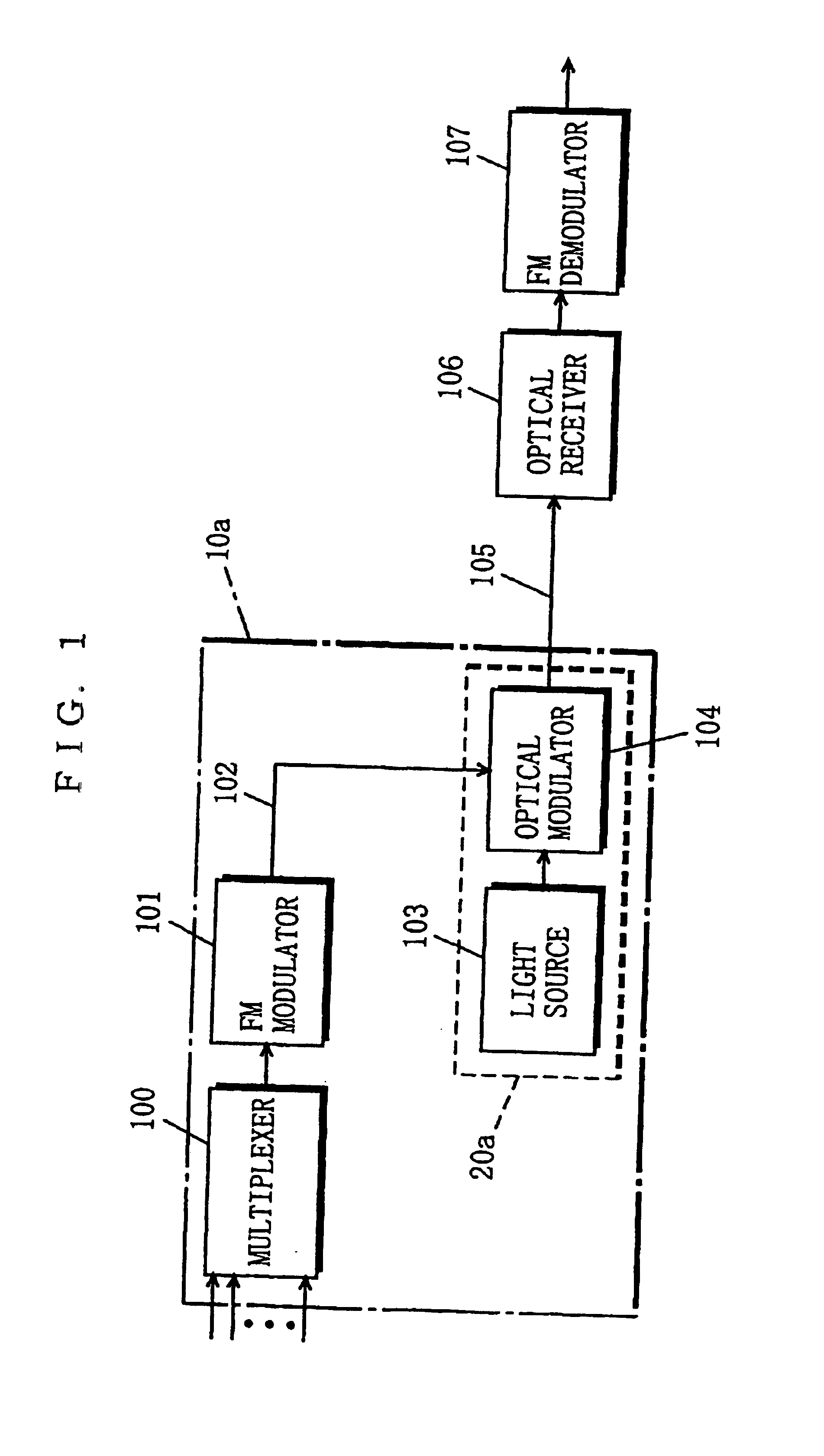
[0055]FIG. 1 shows the configuration of a system for optically transmitting a frequency-division-multiplexed signal according to a first embodiment of the present invention. Referring to FIG. 1, the optical transmission system of the present embodiment comprises a multiplexer 100, an FM modulator 101, a light source 103, an optical modulator 104, an optical receiver 106, and an FM demodulator 107. In the optical transmission system, an electrical transmission line 102 connects the FM modulator 101 and the optical modulator 104 to each other, and an optical transmission line 105 connects the optical modulator 104 and the optical receiver 106 to each other. The optical transmission system transmits an optical signal, which is produced in a below described manner, from a transmitting end to a receiving end through the optical transmission line 105. At the transmitting end, the light source 103 and the optical modulator 104 constitute an optical transmitter 20a, and the optical transmit...

second embodiment

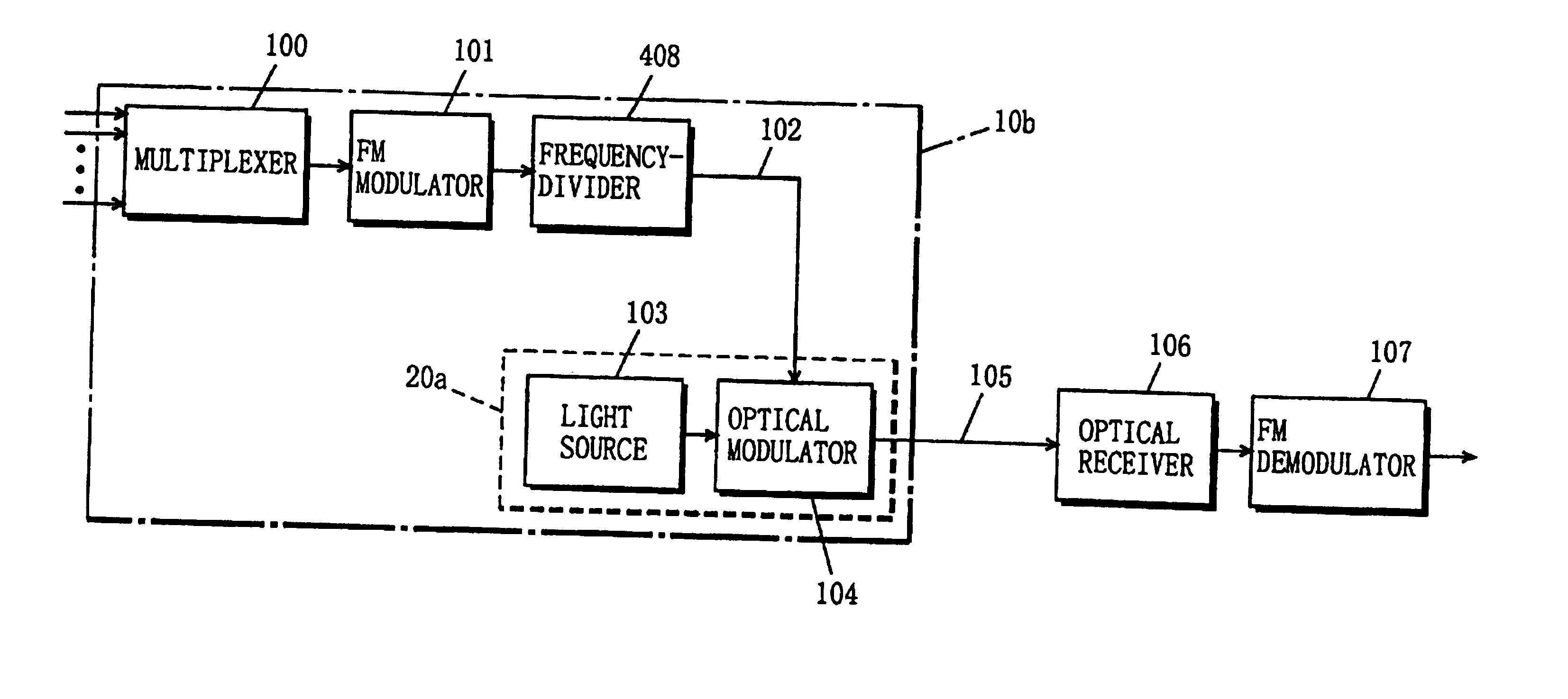
[0059]FIG. 4 shows the configuration of an optical transmission system of an FM modulated signal according to a second embodiment of the present invention. Referring to FIG. 4, the optical transmission system of the present embodiment comprises the multiplexer 100, the FM modulator 101, the light source 103, the optical modulator 104, the optical receiver 106, the FM demodulator 107, and a frequency-divider 408. In the optical transmission system, the electrical transmission line 102 connects the frequency-divider 408 and the optical modulator 104 to each other, and the optical transmission line 105 connects the optical modulator 104 and the optical receiver 106 to each other. The configuration of the second embodiment is different from that of the above-described first embodiment only in including the frequency-divider 408. Therefore, the constituents identical to those in the first embodiment are assigned the same reference numerals, and the description thereof is simplified herei...

third embodiment

[0066]FIG. 7 shows the configuration of an optical transmission system of an FM modulated signal according to a third embodiment of the present invention. Referring to FIG. 7, the optical transmission system of the present embodiment comprises the multiplexer 100, the FM modulator 101, the light source 103, the optical modulator 104, the optical receiver 106, the FM demodulator 107, and an amplitude controller 709. In the optical transmission system, the electrical transmission line 102 connects the amplitude controller 709 and the optical modulator 104 to each other, and the optical transmission line 105 connects the optical modulator 104 and the optical receiver 106 to each other. The configuration of the third embodiment is different from that of the first embodiment in including the amplitude controller 709. Therefore, the constituents identical to those of the first embodiment are assigned the same reference numerals, and the description thereof is simplified herein. The differ...


PUM


Abstract

In an optical transmission system, a multiplexer frequency-division-multiplexes a plurality of signals, and outputs the resultant signal to an FM modulator. The FM modulator converts the frequency-division-multiplexed signal into an FM modulated signal through frequency modulation using the frequency-division-multiplexed signal as an original signal. A frequency-divider converts the FM modulated signal into a frequency-divided FM modulated signal whose frequency is ½n (n is an integer of not less than 1) the frequency of the FM modulated signal. An optical modulator has a predetermined input-voltage vs. output-optical-power characteristic, and is biased at the minimum point (voltage) about the output optical power. The optical modulator modulates an unmodulated light fed from a light source with the applied frequency-divided FM modulated signal to produce an optical signal whose optical carrier component is suppressed, and sends the optical signal to an optical transmission line. An optical receiver receives the optical signal, and square-law detects the signal to convert into an FM modulated signal. A FM demodulator demodulates the FM modulated signal to reproduce the original frequency-division-multiplexed signal. This configuration makes it possible to narrow the bandwidth of an FM modulated signal while increasing the frequency deviation thereof, and realize high-quality signal transmission as a result.

Description

[0001]This application is a reissue application of U.S. Pat. No. 6,486,986, issued Nov. 26, 2002.BACKGROUND OF THE INVENTION[0002]1. Field of the Invention[0003]The present invention relates to optical transmission systems, and more particularly to a system that optically transmits a frequency-division-multiplexed signal obtained by frequency-division-multiplexing a plurality of signals.[0004]2. Description of the Background Art[0005]FIG. 11 is a block diagram exemplarily showing the configuration of a conventional optical transmission system for transmitting a frequency-division-multiplexed signal. As will be known from FIG. 11, this optical transmission system comprises a multiplexer 1100, an FM modulator 1101, an optical transmitter 1104, an optical receiver 1106, and an FM demodulator 1107. In the optical transmission system, an electrical transmission line 1102 connects the FM modulator 1101 and the optical transmitter 1104 to each other, and an optical transmission line 1105 c...

Claims


Application Information

Patent Timeline
Patent Type & Authority Patents(United States)
IPC IPC(8): H04B10/18H04B10/152H04B10/155H04J14/02H04J14/00H04B10/2513H04B10/516H04B10/548H04B10/564H04B10/588H04B10/61
CPCH04B10/25137H04B10/505H04B10/5165H04J14/0298
Inventor FUSE, MASARU
Owner PANASONIC CORP
Why Eureka
Try Eureka