

Optical filter and optical module having optical filter
a technology of optical filters and optical modules, applied in the direction of mirrors, instruments, mountings, etc., can solve the problems of severe adverse effects on the spectral characteristics of extracted light, and achieve the effects of excellent spectral characteristics, high maximum transmittance, and narrow half-bandband
- Summary
- Abstract
- Description
- Claims
- Application Information
AI Technical Summary
Benefits of technology
Problems solved by technology
Method used
Image

Examples
first embodiment
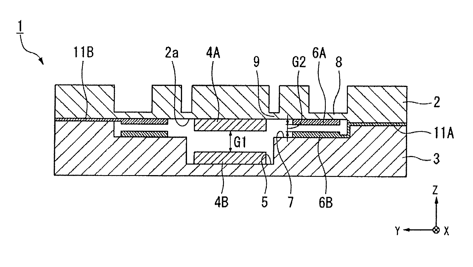
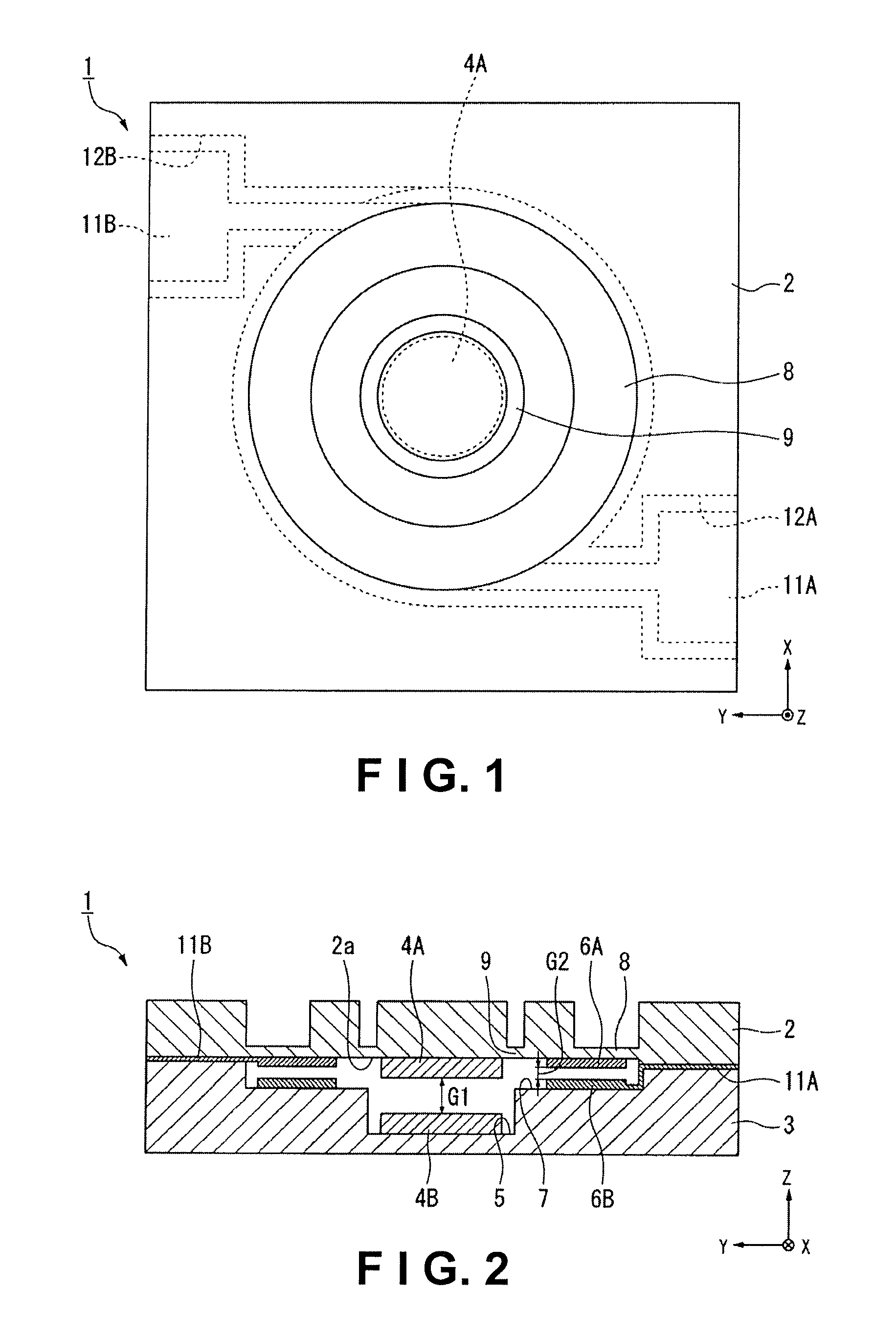
[0047]FIG. 1 is a plan view showing the optical filter of the present embodiment, and FIG. 2 is a sectional view showing the optical filter of the present embodiment. In the drawings, the reference numeral 1 refers to an optical filter including an air-gap-type electrostatically actuated etalon element, and this optical filter 1 includes a first substrate 2; a second substrate 3 joined (or bonded) to the first substrate 2 so as to face the first substrate 2; a circular mirror 4A (a mirror member) provided at the center of an opposing surface 2a of the first substrate 2; a circular mirror 4B (a mirror member) provided to the bottom of a first cavity 5 formed in the center of the second substrate 3, the circular mirror 4B being provided opposite the mirror 4A across a first gap G1; a ring-shaped electrode 6A provided on the periphery of the mirror 4A of the first substrate 2; a ring-shaped electrode 6B provided in a shallow ring-shaped second cavity 7 formed on the periphery of the fi...
second embodiment
[0075]FIG. 6 is a sectional view showing the optical filter of the present embodiment, and FIG. 7 is an enlarged sectional view showing the relevant portion of FIG. 6.
[0076]In the optical filter 1 of the first embodiment, the ring-shaped diaphragm portion 9 having a thickness equal to or less than that of the diaphragm portion 8 is formed at a predetermined interval in the first substrate 2 and on the inner peripheral side of the diaphragm portion 8, whereas the optical filter 21 of the present embodiment differs from the optical filter 1 of the first embodiment in that the diaphragm portions 8, 9 are integrated to form a single wide ring-shaped diaphragm portion 22. The other constituent elements of the optical filter 21 of the present embodiment are the same those of the optical filter 1 of the first embodiment.
[0077]The shape or thickness of the diaphragm portion 22, and other characteristics are arbitrary insofar as light in the desired wavelength range is emitted. Specifically,...
third embodiment
[0081]FIG. 8 is a plan view showing the optical filter of the present embodiment, and FIG. 9 is a sectional view showing the optical filter of the present embodiment.
[0082]In the optical filter 1 of the first embodiment, the first substrate 2 is formed by glass or another optical transparent material, the electrodes 6A, 6B are provided to the first substrate 2 and second substrate 3 so as to face each other across the second gap G2, the ring-shaped diaphragm portion 8 is formed in a position substantially corresponding to the outer peripheral portion of the electrode 6A in the first substrate 2, and the ring-shaped diaphragm portion 9 having a thickness equal to or less than that of the diaphragm portion 8 is formed on the inner peripheral side of the diaphragm portion 8. However, the optical filter 31 of the present embodiment differs from the optical filter 1 of the first embodiment in that a first substrate 32 is formed using silicon or another semiconductor material, the electro...
PUM
 Abstract
Description
Claims
Application Information