
Bandwidth-limited and long pulse master oscillator power oscillator laser systems

a laser system and master oscillator technology, applied in the direction of laser details, optical resonator shape and construction, active medium materials, etc., can solve the problems of limited stretching ratio of pulses, add to energy inefficiency, and energy inefficient, so as to reduce power density and reduce power density on telescope mirrors.

Inactive Publication Date: 2006-01-12
COHERENT GMBH
View PDF16 Cites 40 Cited by
  • Summary
  • Abstract
  • Description
  • Claims
  • Application Information

AI Technical Summary

Benefits of technology

"The present invention is about a laser system that includes a master oscillator and a power oscillator. The power oscillator has a resonator with a bandwidth-restricting element, such as a prism, to amplify the laser pulse. The resonator can be a ring resonator or a linear resonator with a length of at least 2 meters. This allows for a longer pulse length and reduces the possibility of optical damage to the outcoupling mirror. The long resonator also provides an option of using a grazing incidence reflective telescope to expand the light beam and reduce power density on the outcoupling mirror. The technical effects of the invention include improved laser pulse amplification and reduced optical damage."

Problems solved by technology

One limitation the passive pulse-stretcher is that it is energy inefficient.
This is due to scatter and absorption losses at the beamsplitter and components of the optical delay line.
Another limitation is that the stretching ratio of the pulse is limited.
In a case where the pulse has to be stretched by a greater factor, two or more consecutive pulse-stretchers have to be used, which adds to energy inefficiency.
Energy inefficiency converts to higher cost of the system and higher operating cost of the system.
A conventional, single-oscillator, excimer laser cannot provide the required high output power with the required narrow spectral emission bandwidth.
These two requirements are in conflict with each other, since for obtaining the narrow bandwidth the oscillator must run at low output power.
At higher powers, sophisticated means for spectral line narrowing including prisms and gratings cannot be employed.
However, the power extraction efficiency is limited, especially if the master oscillator emits low power.
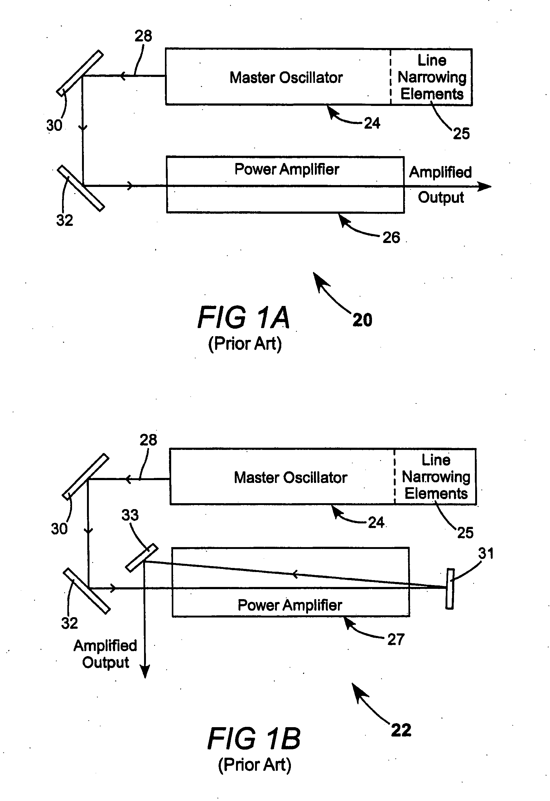
For a multiple pass amplifier, such as illustrated in FIG. 1B, the setup quickly becomes complicated, as the output and input beams have to be spatially separated.
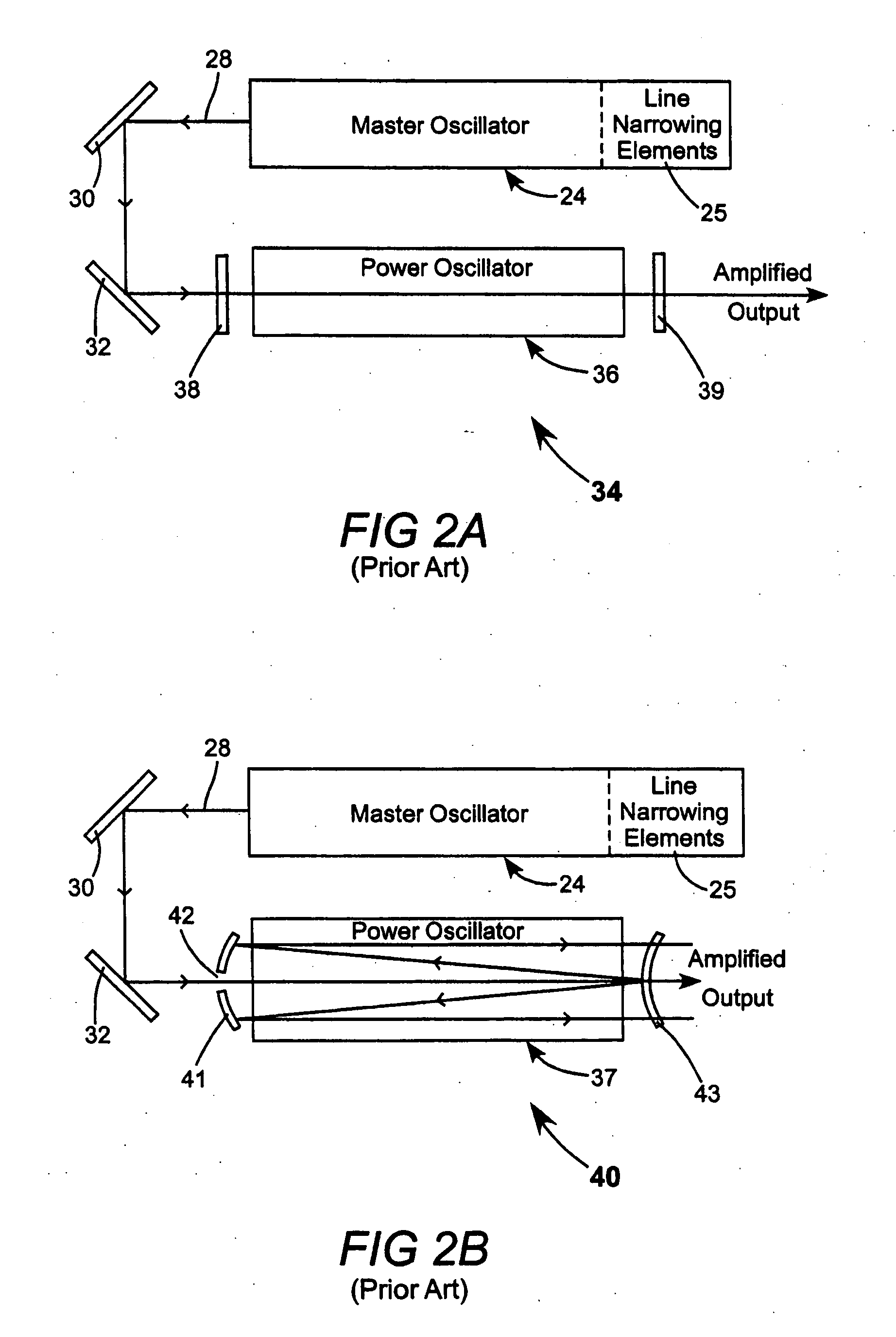
In a MOPO system, however, degradation of internal optical components due to exposure to high energy UV radiation occurs more rapidly than in a MOPA laser.
Also, if seeding is insufficient, a background of broad emission characteristics will overlay the narrow bandwidth spectrum of the seed source.
Such background is highly undesirable, especially for lithography applications.
Another disadvantage of a MOPO laser system results from cross talk between the master oscillator and the power amplifier.
This cross talk can degrade the performance of the master oscillator.
Such a delay line, however, consumes valuable space inside a laser enclosure.
This option, unfortunately, is not feasible for a linear power oscillator.

Method used


Image

  • Bandwidth-limited and long pulse master oscillator power oscillator laser systems
  • Bandwidth-limited and long pulse master oscillator power oscillator laser systems
  • Bandwidth-limited and long pulse master oscillator power oscillator laser systems

Examples


embodiment 110

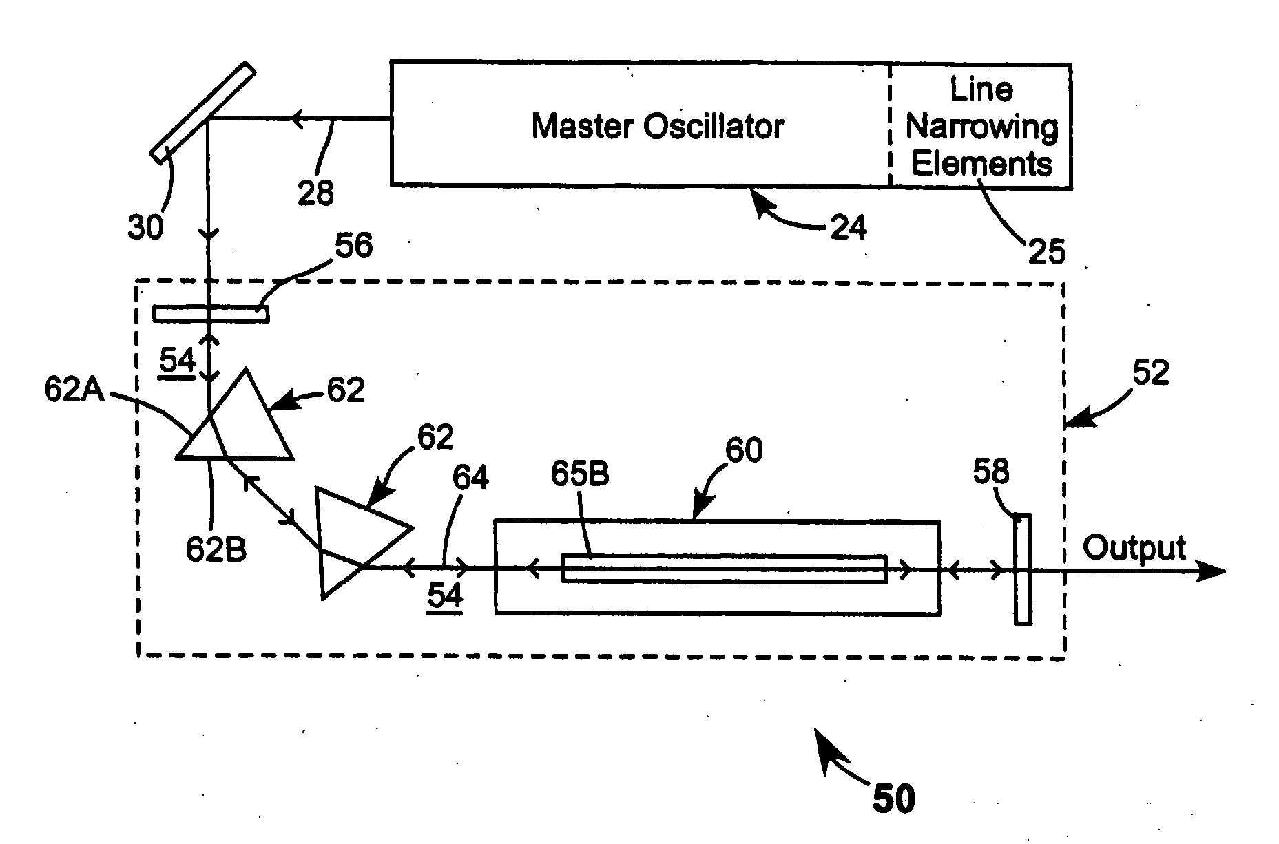
[0085]FIG. 13 is a long beam-axis view schematically illustrating a ninth preferred embodiment 110 of a MOPO in accordance with the present invention including a master oscillator 24 having line-narrowing elements 25, and a BLPO 112 including a ring resonator 114. Ring resonator 114 includes a gain chamber 60 and two Pellin-Broca prisms 104. Pellin-Broca prisms 104 serve as fold mirrors for resonator 114. Each of the Pellin-Broca prisms is arranged as a beam compressor, as discussed above with reference to FIG. 12A, for compensating for natural divergence of a laser beam circulating in the resonator. In the relative (orientation) orientation shown, with each of the prisms (prism faces) in a non-Brewster alignment with the circulating beam the prisms also provide some limited dispersion as discussed above. Ring resonator 114 is completed by two fully reflective fold mirrors 120 and 122, a partially transmissive fold mirror 124, and a prism 126 having a face 126A thereof arranged such...

embodiment 130

[0088]FIG. 14 is a long beam-axis view schematically illustrating a tenth preferred embodiment 130 of a MOPO in accordance with the present invention, having a master oscillator 24 including line-narrowing elements 25, and a BLPO 132 including a ring resonator 134. Ring resonator 134 includes a gain chamber 60 and two Pellin-Broca prisms 104. Pellin-Broca prisms 104 serve as fold mirrors for resonator 134. In this relative orientation the beams provide a relatively high dispersion. In resonator 134 each of the Pellin-Broca prisms is arranged to turn light though 90° as discussed above with reference to FIG. 12. A beam entering and leaving the prisms has the same width and is incident on refractive surfaces of the prism at the Brewster angle. Accordingly, there is no beam compression. Ring resonator 114 is completed by a fully reflective fold mirror 92, and a partially transmissive fold mirror 90 that serves as an outcoupling mirror. A seed beam 28 from master oscillator 24 is inject...

embodiment 206

[0113]FIG. 23 is a long beam-axis view schematically illustrating a sixteenth embodiment 206 of a MOPO laser in accordance with the present invention. MOPO 206 has a master oscillator 24 including line narrowing elements 25, and a power oscillator 208. Power oscillator 208 has a ring-resonator 115 with optical elements thereof arranged similarly to those of resonator 114 of power oscillator 112 of FIG. 13. Surface 126A of a prism 126 serves as a beamsplitter for coupling a portion of circulating laser radiation out of the resonator as in the above-described resonator. The circulating beam is incident at grazing incidence on surface 126A for expanding the beam and thereby reducing optical fluence on the surface.

[0114] In resonator 115 of FIG. 23, prism 126 is located in a gain chamber 61. Gain chamber 61 has a section 61A thereof including discharge electrodes (only lower electrode 65B shown) and a portion 61B thereof including prism 126. A front Brewster angle window 67 is located i...


PUM


Abstract

Laser systems have a line-narrowed master oscillator and a power oscillator for amplifying the output of the master oscillator. The power oscillator includes optical arrangements for limiting the bandwidth of radiation that can be amplified. The limited amplification bandwidth of the power oscillator is relatively broad compared to that of the output of the master oscillator, but narrower than would be the case without the bandwidth limiting arrangements. The bandwidth narrowing arrangements of the power oscillator function primarily to restrict the bandwidth of amplified spontaneous emission generated by the power oscillator.

Description

PRIORITY [0001] This application claims priority from U.S. Provisional Application Ser. No. 60 / 586,768, filed Jul. 9, 2004, and is incorporated herein by reference.TECHNICAL FIELD OF THE INVENTION [0002] The present invention relates generally to master oscillator, power oscillator (MOPO) laser systems. The invention relates in particular to molecular fluorine (F2) or excimer MOPO laser systems including arrangements for spectral narrowing, long pulse generation, extending component lifetime, or reduction of amplified spontaneous emission (ASE). DISCUSSION OF BACKGROUND ART [0003] Excimer lasers including MOPO systems and master oscillator power amplifier (MOPA) systems are extensively used as light sources for UV microlithography in the manufacture of state-of-the-art semiconductor integrated circuits. Such excimer lasers have to satisfy challenging and often mutually conflicting technical requirements, due to an ever-increasing demand for smaller critical dimensions of the integra...

Claims


Application Information

Patent Timeline
Patent Type & Authority Applications(United States)
IPC IPC(8): H01S3/22
CPCH01S3/08031H01S3/083H01S2301/02H01S3/10092H01S3/225H01S3/097
Inventor GOVORKOV, SERGEI V.WIESSNER, ALEXANDER O.W.MISYURYAEV, TIMUR V.JACOBSON, ALEXANDERHUA, GONGXUEPAETZEL, RAINERSCHROEDER, THOMASALBRECHT, HANS-STEPHAN
Owner COHERENT GMBH
Learn More