Redundant network interface for ethernet devices

a network interface and ethernet device technology, applied in the field of redundant network switches, can solve the problems of increasing network load, significant limitations to the usefulness of using these network switches to connect to independent networks, and removing independen

Inactive Publication Date: 2008-06-24
RED LION CONTROLS
View PDF5 Cites 45 Cited by
  • Summary
  • Abstract
  • Description
  • Claims
  • Application Information

AI Technical Summary

Benefits of technology

[0012]This invention disclosed herein is a network switch which is easily configured by a user possessing limited technical knowledge. The simplicity of this invention enhances reliability (through its simplicity), reduces installation time and skill level required, makes it practical to swap these devices when repairs are necessary, and makes it possible to view or control the flow of network traffic through commercially available industrial controllers or software.
[0013]The invention is built upon the observation that it is desirable for one or more Ethernet devices to communicate to each of two or more independent networks through “uplink” ports, and that as long as the uplink ports are not permitted to send messages between themselves, independence (i.e., segregation) of the networks is maintained. This embodiment uses an unmanaged network switch that is given a special rule to never pass messages from one uplink port to any other port designated as an uplink port. In this way, segregated traffic on the independent networks is maintained. An added benefit of this embodiment is that devices connected to the ports other than the uplink ports (i.e., local ports), may freely communicate amongst themselves, without restriction, and with the added benefit of improved network bandwidth by segregating local network traffic from wide area network traffic. All other benefits of the unmanaged network switch are maintained, such as avoidance of collisions, and limitation of broadcast message bandwidth.

Problems solved by technology

The vast majority of Ethernet devices have only a single Ethernet port, and / or either limited or no capabilities to make multiple, independent connections.
There are significant limitations to the usefulness of using these network switches to make connection to independent networks.
a) Unmanaged network switches pass messages from one network to the other, thus removing independence of the networks. This unwanted traffic increases network loading; can breach security through the undesirable transmission of messages; and can cause network conflicts if, for example, duplicate addressing is in use on the independent networks.
b) In the case of applications utilizing redundant network paths, unmanaged network switches could send messages back to network nodes that have received this message already from another path. This undesired event could cause unacceptable confusion on the network.
c) In redundant network schemes it is desirable to know when a failure in one of the network paths occurs so that a repair can be made. Network switches do not identify the path of the message for this purpose.
d) While many of these limitations can be overcome with a managed network switch or router, these complex devices require configuration and careful network planning. Further, the addition of new devices on the network or changes in the network topology can require reconfiguration for continued operation.

Method used


Image

  • Redundant network interface for ethernet devices
  • Redundant network interface for ethernet devices
  • Redundant network interface for ethernet devices

Examples


Embodiment Construction

[0028]The following is a detailed explanation of the structure and method for a method and apparatus for a redundant network switch which is able to interface with and segregate two or more independent networks. For the purposes of illustration, these networks will be referred to as Ethernet networks herein. It should be noted that the same reference numbers are assigned to components having approximately the same functions and structural features in the following explanation and the attached drawings to preclude the necessity for repeated explanation thereof.

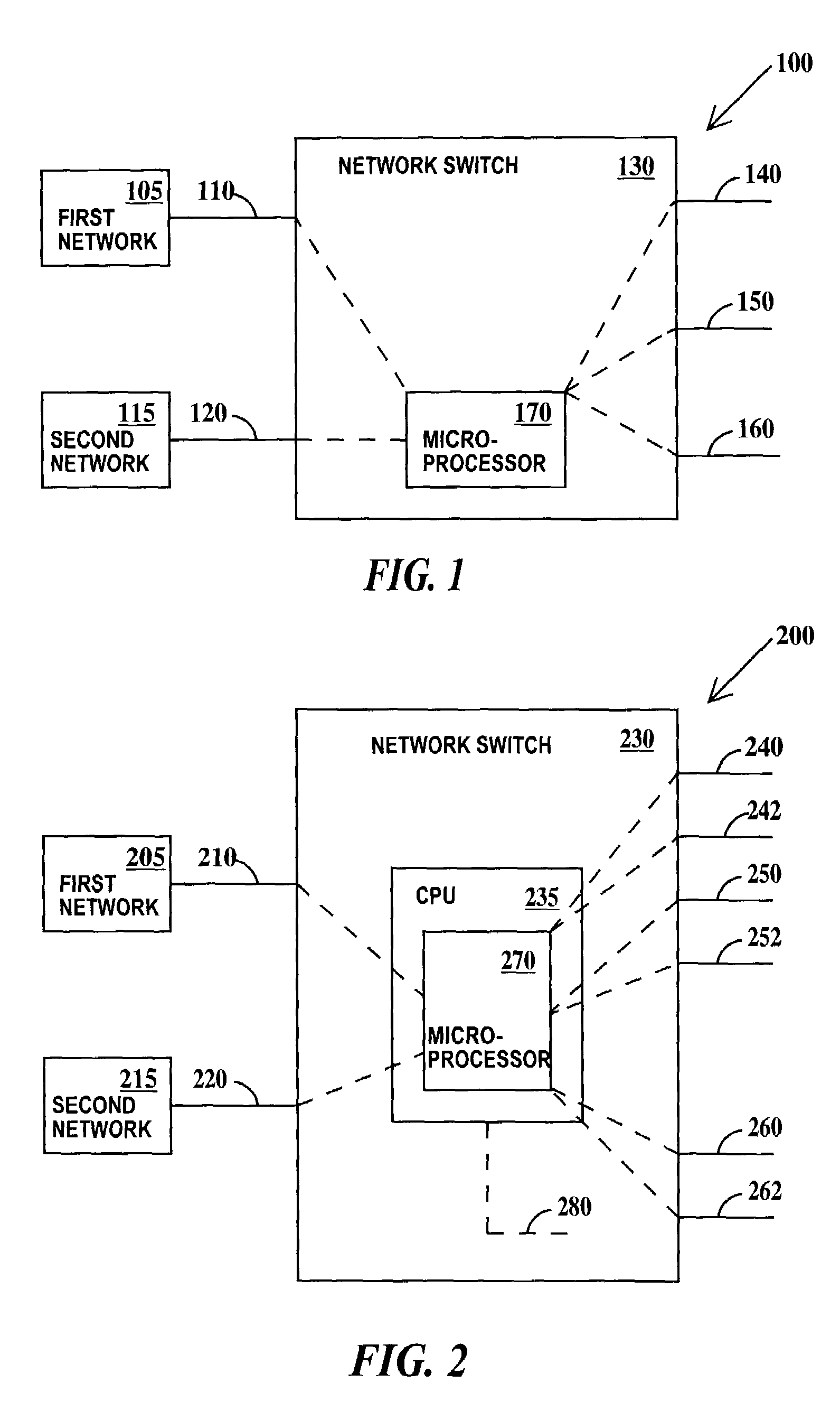
[0029]According to a general illustrative embodiment of the present invention, shown schematically in FIG. 1, the illustrative system 100 described herein includes a network switch 130 which will function as an element in a larger network, for example, in an Ethernet network. An Ethernet network, as discussed herein including VLAN (to be discussed infra), is a local area network wherein data is broken into packets and transmitt...


PUM


Abstract

A redundant network interface for ethernet devices is disclosed. The redundant network interface provides connections between one or more Ethernet devices and two or more independent networks. The redundant network interface device also tests an active primary Ethernet connection path, and when a failure or inactive path is detected, the redundant network interface device reroutes the messages to alternate communication path.

Description

BACKGROUND OF THE INVENTION[0001]1. Technical Field[0002]The invention relates generally to a network switch for communications networks, and more particularly to a redundant network switch which is able to interface with and segregate two or more independent Ethernet networks. A method of using the redundant network switch interface device is also presented.[0003]2. Related Art[0004]It is often desirable to form multiple connections to devices on an Ethernet network to enhance reliability, or to connect one or more Ethernet device(s) to two independent networks. The vast majority of Ethernet devices have only a single Ethernet port, and / or either limited or no capabilities to make multiple, independent connections.[0005]Local Ethernet devices are commonly connected to an Ethernet network by use of a device known as an Ethernet hub or network switch. These devices typically make the required connections with no regard to segregation or restriction of network traffic. There are signi...

Claims


Application Information

Patent Timeline
Patent Type & Authority Patents(United States)
IPC IPC(8): G01R31/08H04L12/56
CPCH04L49/351H04L49/354
Inventor ELLIS, DAVID G.SCHOENBERG, STEVEN A.
Owner RED LION CONTROLS
Why Eureka
Try Eureka