

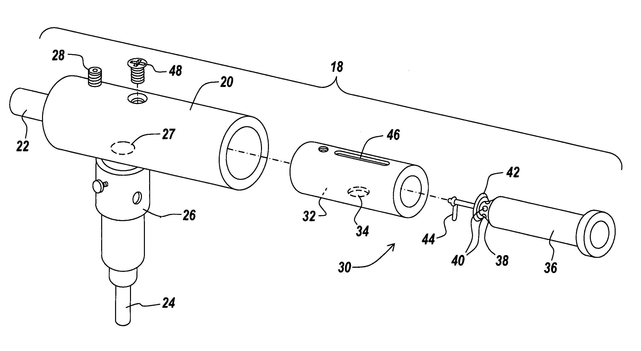
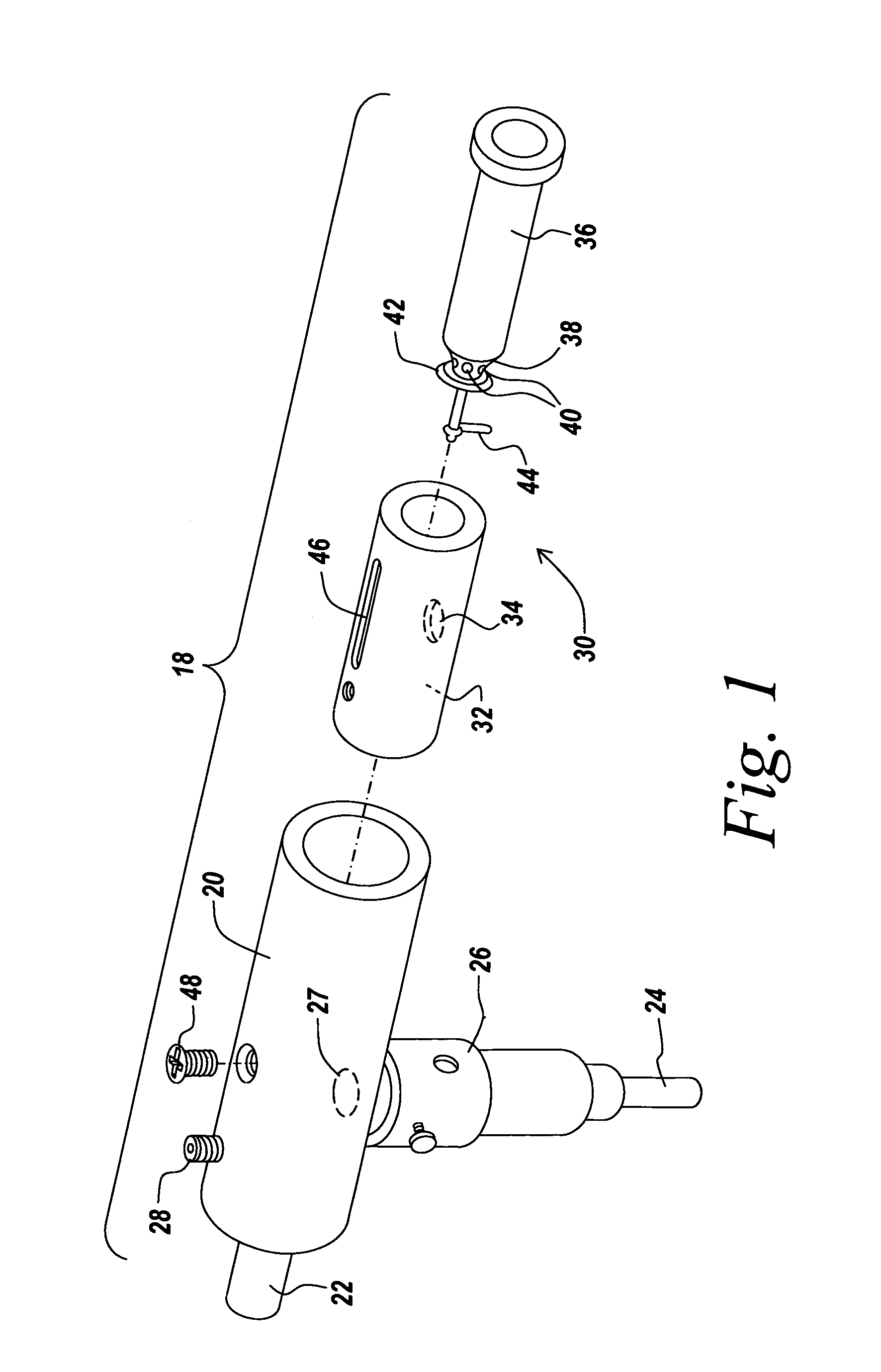
Inexsufflator
a technology of inexsufflator and airway, which is applied in the direction of respirator, operating means/releasing devices of valves, building rescue, etc., can solve the problems of high risk of severe, potentially fatal, pneumonia, physical trauma to the airway of the patient, infection within the patient's airway, etc., and achieves clear and simple respiratory secretions.
- Summary
- Abstract
- Description
- Claims
- Application Information
AI Technical Summary
Benefits of technology
Problems solved by technology
Method used
Image

Examples
first embodiment
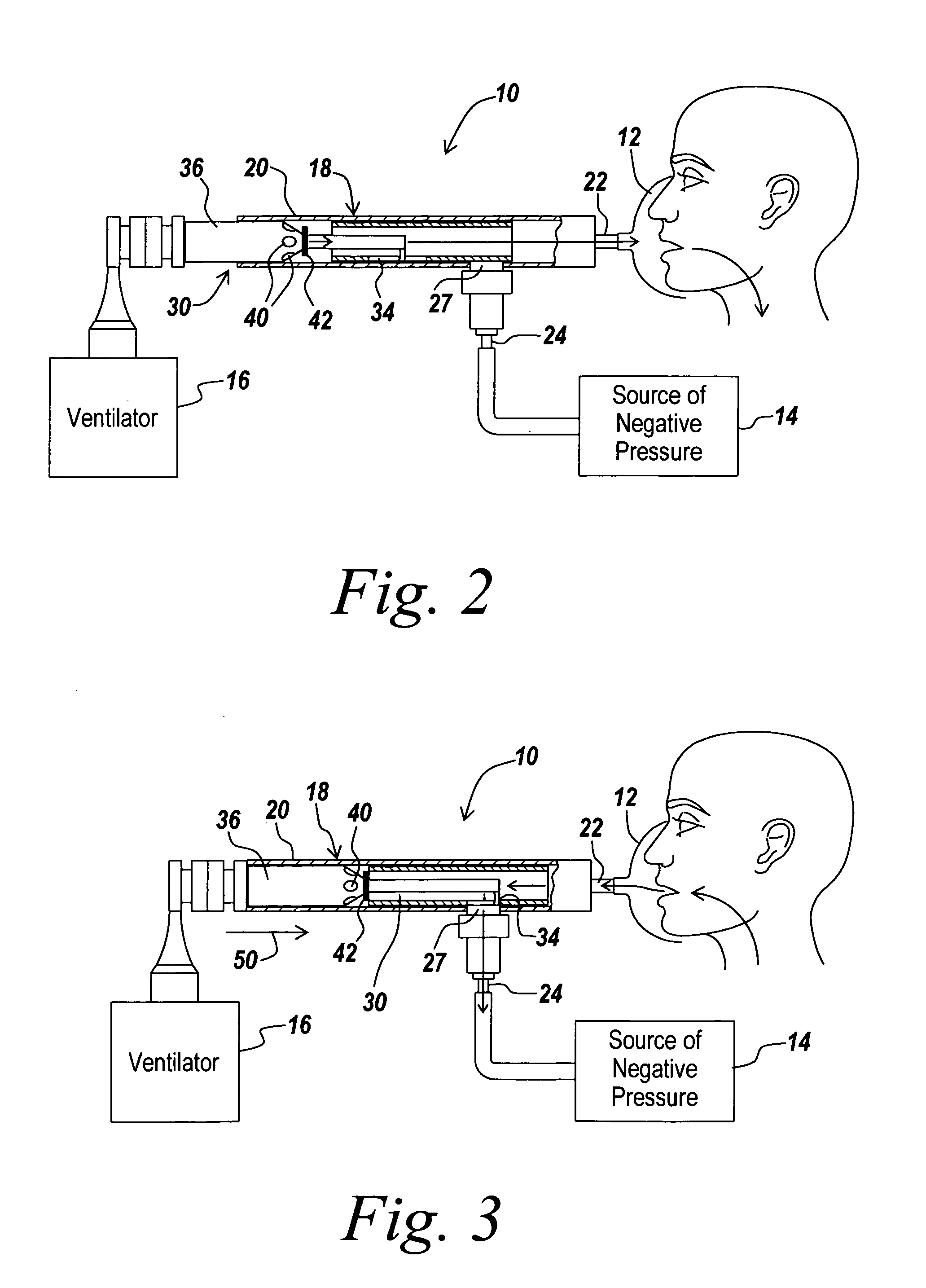
[0053]In the current invention, source 16 of positive fluid pressure is a hand-held “AMBU” type manual resuscitator bag, for example, an MR-100 Adult Resuscitator (Galemed Corp. Taiwan). In terms of this embodiment, the phase of insufflation is initiated by the user manually squeezing the manual resuscitator bag so as to generate positive pressure within the patient's airways, as depicted by pressure sensor 28. Thereafter, the working cycle of inexsufflator 10 is generally as described previously. In terms of this embodiment of inexsufflator 10, intrapulmonary pressure returns to atmospheric pressure during the pause period between the termination of exsufflation and the initiation of the next insufflation.
second embodiment
[0054]In a second embodiment, source 16 of positive fluid pressure is a standard volume-cycled or time-cycled pressure-limited ventilator, for example, an LP-10 Volume Ventilator (Nellcor Puritan Bennet Inc. Pleasanton, Calif.) or an LTV-1000 Ventilator (Pulmonetic Systems, Colton, Calif.). A volume-cycled ventilator is a ventilator in which the amount of air delivered to the patient by the ventilator with each inspiration is a predefined volume of air. In other words, the ventilator terminates airflow and ends the phase of inspiration when a predefined volume of air has entered the patient. This is to be contrasted with a time-cycled ventilator, in which the amount of air delivered to the patient by the ventilator with each inspiration is of an a-priori undefined volume, and the ventilator terminates airflow and ends the phase of inspiration when a predefined inspiratory time has been achieved. Similarly, standard inexsufflators, such as the CoughAssist Inexsufflator, terminate pos...
third embodiment
[0056]In the present invention, source 16 of positive fluid pressure is a ventilator that is capable of generating positive pressure within the patient's airway during expiration, such as a BiPAP Synchrony Ventilator (Respironics Inc. Pittsburgh, Pa.). In this embodiment, prior to initiating the working cycle as described above, the user sets ventilation parameters for the BiPAP ventilator so as to achieve maximal insufflation with each delivered ventilator breath (by choosing an appropriate value for the inspiratory positive airway pressure—“IPAP”) and so as to achieve a desired expiratory positive airway pressure between inexsufflation cycles, i.e. during the ventilator's expiratory cycle. Thereafter, the working cycle of inexsufflator 10 is generally as described previously. During the pause period between the termination of exsufflation and the initiation of the next insufflation by the ventilator, intrapulmonary pressure may be maintained at a supra-atmospheric PEEP level by th...
PUM
 Abstract
Description
Claims
Application Information