
One way brake for a cordless blind

a cordless blind and one-way brake technology, applied in the direction of shutters/movable grilles, door/window protective devices, wing arrangements, etc., can solve the problems of cost-intensive assembling and manufacturing of friction systems, small children and pets' safety concerns, and the cordless blinds do not lend themselves to size-in-store adjustmen

Inactive Publication Date: 2006-08-29
HUNTER DOUGLAS INDS SWITZERLAND
View PDF87 Cites 47 Cited by
  • Summary
  • Abstract
  • Description
  • Claims
  • Application Information

AI Technical Summary

Benefits of technology

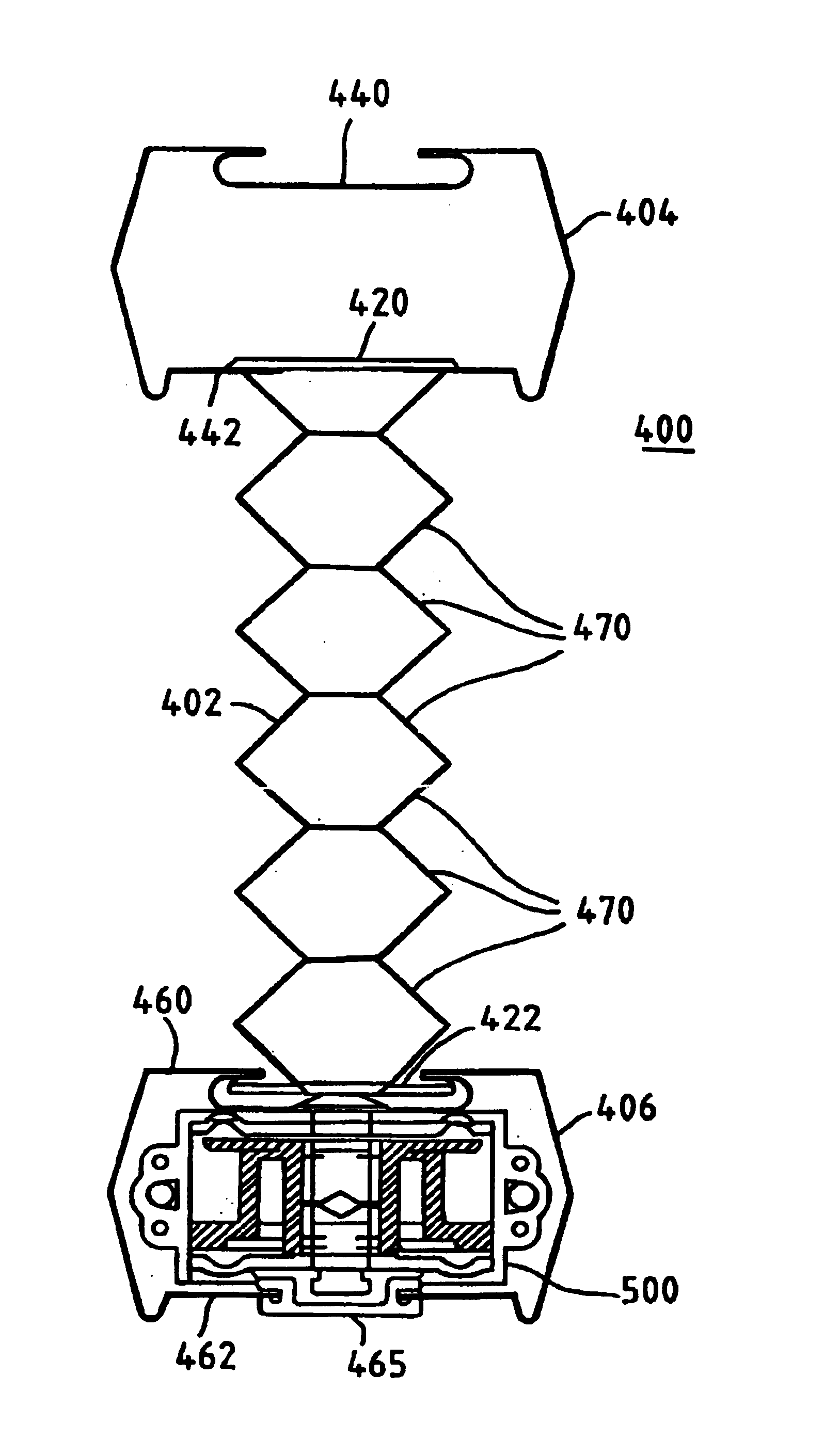
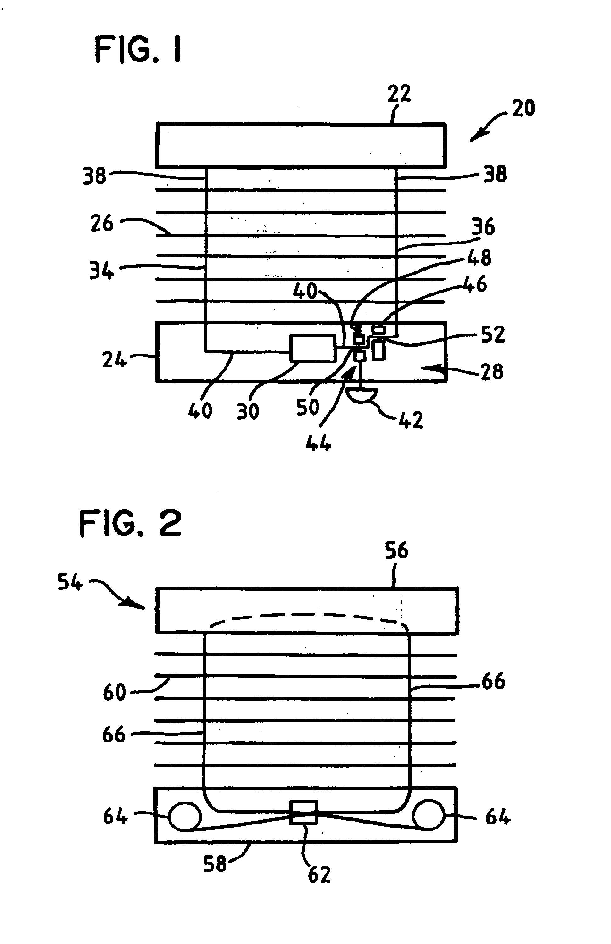
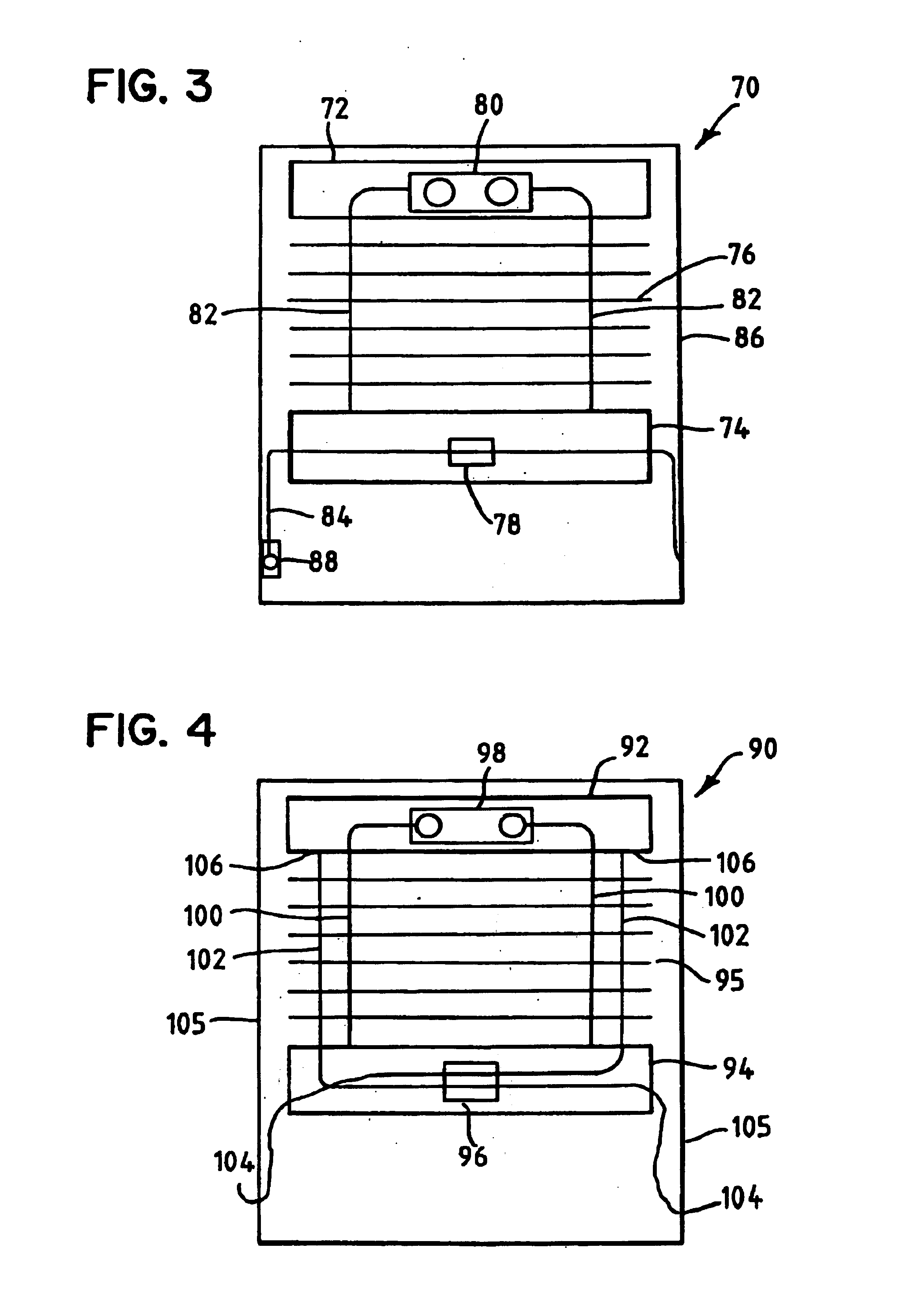
[0013]These and other advantages and features of the present invention may also be accomplished in a window covering comprising a head rail, a bottom rail, a window covering material extending between the head rail and bottom rail, first and second lift cords extending between the head rail and the bottom rail, a biasing element configured to bias the bottom rail toward the head rail, and operatively coupled to the first and second lift cords, and a brake assembly configured to inhibit movement of the bottom rail. The brake assembly includes a brake releasably coupled to the biasing element, a brake lever pivotally coupled to the bottom rail, and a user interface operatively coupled to the brake lever and configured to pivot it to a first position wherein the brake is in an engaged position and a second position wherein the brake is in a disengaged position.

Problems solved by technology

However, such an arrangement may present a safety concern to small children and pets.
However, such known cordless blinds have several disadvantages for a mass-merchandise avenue of distribution, including, for example, the need for friction systems that are costly to assemble and manufacture.
Also, these cordless blinds do not lend themselves to size-in-store adjustment.
However, because the cord brake mechanism is located in the bottom rail while the spring motor is in the head rail and the lift cords connect the bottom rail to the head rail, it is only useful to prevent the bottom rail from free falling.
Also, opening of blind requires the user to exert effort to lift bottom rail and patience to wait for the weak spring retrieving units to wind up the slack cords.

Method used


Image

  • One way brake for a cordless blind
  • One way brake for a cordless blind
  • One way brake for a cordless blind

Examples


Embodiment Construction

[0046]The embodiments illustrated in FIGS. 1-10 apply a braking mechanism to ensure that the bottom rail does not move (e.g. from accumulator weight of bottom rail and slats or from the spring force).

[0047]To ensure that the bottom rail does not move downward without additional force (commonly referred to as “creep”), the combined weight of the bottom rail (BRw) and the accumulated window covering (WCw) must be less than the forces resisting downward movement including the system friction (Ffd) resisting downward movement and the spring force of the spring motor (SMf). This can be expressed as (BRw+WCw)<(SMf+Ffd). The system friction (Ff) tends to oppose movement in both directions, although not necessarily with the same force, depending on the source of the system friction. Accordingly, system friction that opposes downward movement of the bottom rail will be designated Ffd and system friction that opposes upward movement of the bottom rail will be designated Ffu.

[0048]To ensure th...


PUM


Abstract

A window covering including a head rail, a bottom rail, a window covering material extending between the head rail and bottom rail, a first and second lift cords extending between the head rail and the bottom rail, a spring motor configured to bias the bottom rail toward the head rail, mounted in the bottom rail, and operatively coupled to the first and second lift cords, and a brake mounted in the bottom rail and configured to releasably couple to the first lift cord to prohibit the spring motor from taking up the first cord, prohibiting the bottom rail from being raised or lowered.

Description

CROSS REFERENCE TO RELATED APPLICATION[0001]This application is a non-provisional continuation-in-part (CIP) application claiming priority from Non-Provisional application Ser. No. 10 / 016,981, entitled “Brake for a Cordless Blind” filed Dec. 14, 2001 now U.S. Pat. No. 6,675,861.FIELD OF THE INVENTION[0002]The present invention relates to a system in which outer lifting cords are eliminated from shades or blinds. More specifically, the present invention relates to window covering systems including without limitation custom sizable window covering systems that employ one or more springs to accumulate the lifting cord within the head rail and / or bottom rail as the blind or shade is raised or lowered and a brake to secure the bottom rail in a static position.BACKGROUND OF THE INVENTION[0003]It is generally known to provide for a window covering venetian blind with the slats that are raised and lowered by a pair of lift cords. Such known window coverings typically include lift cords that...

Claims


Application Information

Patent Timeline
IPC IPC(8): E06B9/30E06B9/322E06B9/60E06B9/90
CPCE06B9/322E06B9/90E06B9/60
Inventor CIUCA, ZAZUPALMER, ROGER
Owner HUNTER DOUGLAS INDS SWITZERLAND
Learn More