
Rotary cutter for a wood planing machine

a technology of rotary cutter and wood planing machine, which is applied in the direction of shaping cutter, flat surface machine, manufacturing tools, etc., can solve the problem of difficult maintenance of the precise alignment of the blades of the 16-blade system

Inactive Publication Date: 2006-09-05
SHINMAX IND
View PDF4 Cites 6 Cited by
  • Summary
  • Abstract
  • Description
  • Claims
  • Application Information

AI Technical Summary

Problems solved by technology

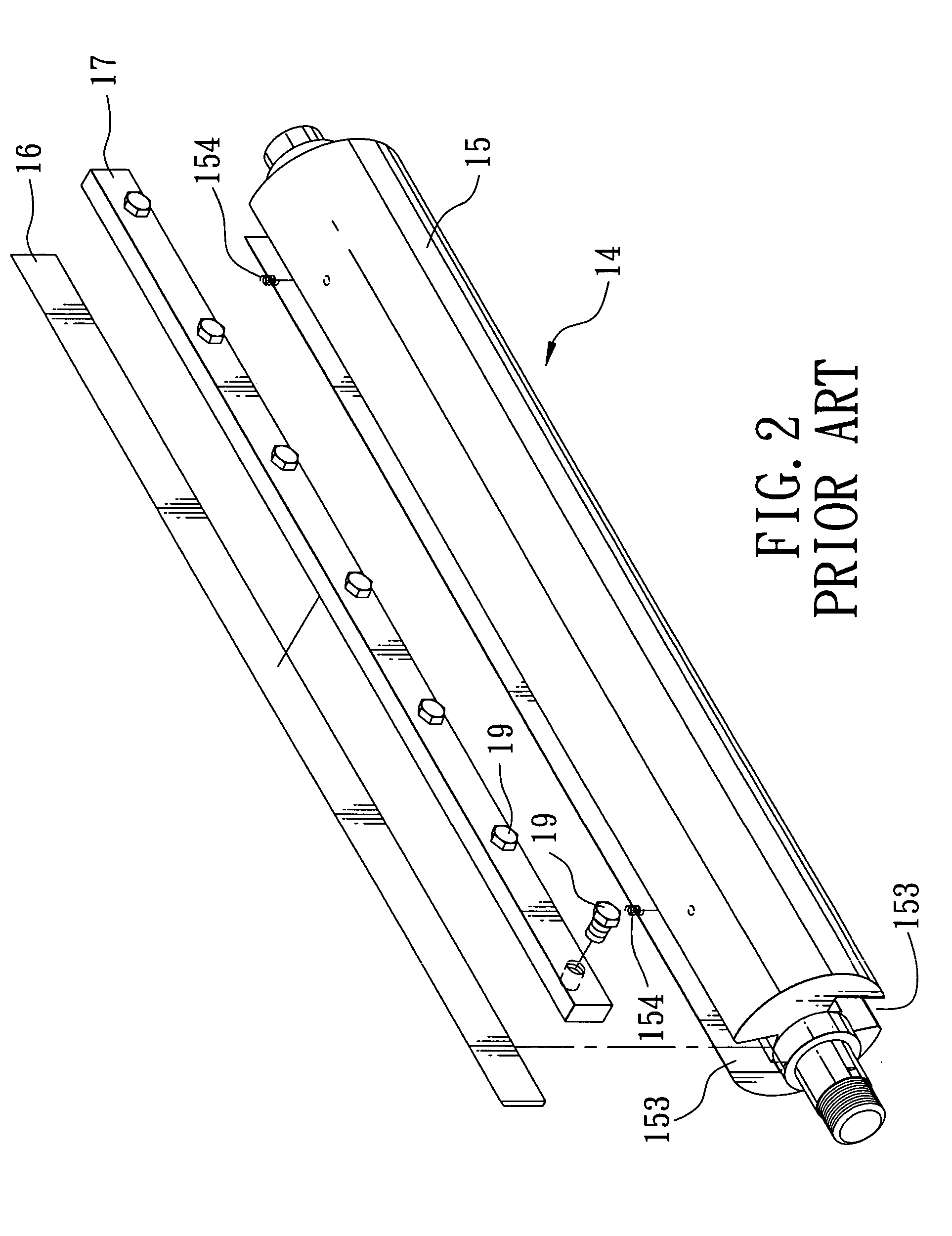
Moreover, since the urging members 154 are likely to deform after a period of use and since the extent of deformation is not likely to be the same for the urging members 154, precise alignment of each blade 16 can be difficult to maintain.

Method used


Image

  • Rotary cutter for a wood planing machine
  • Rotary cutter for a wood planing machine
  • Rotary cutter for a wood planing machine

Examples


Embodiment Construction

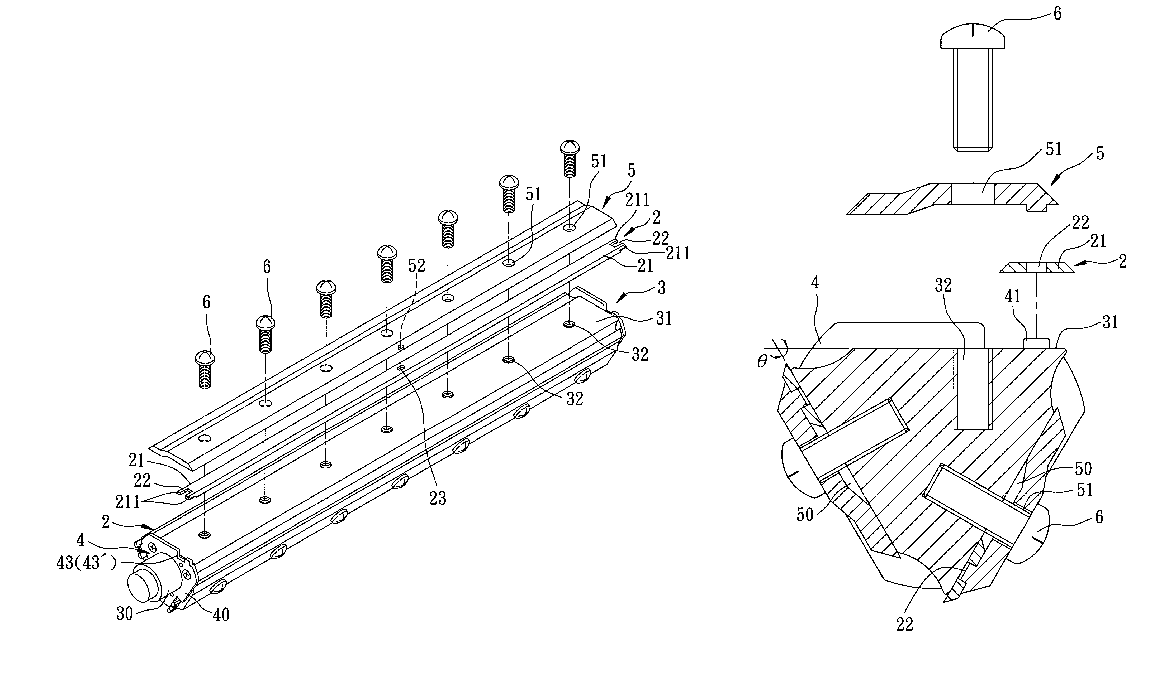
[0017]FIGS. 4 to 6 illustrate the preferred embodiment of a rotary cutter for a wood planing machine according to this invention.

[0018]The rotary cutter includes: an elongated shaft 3 that defines a rotation axis, that has two opposite mounting ends 30, and at least one axially extending blade-mounting surface 31 parallel to the rotation axis and extending between the mounting ends 30, and that is formed with threaded holes 32 indented inwardly from the blade-mounting surface 31 and aligned in an axial direction relative to the rotation axis; a pair of blade-aligning members 4, each of which is mounted on a respective one of the mounting ends 30 of the shaft 3, and each of which is formed with at least one protrusion 41; at least one blade 2 attached to the blade-mounting surface 31 and having two opposite end portions 21, each of which is formed with a first recess 22 that receives the protrusion 41 of a respective one of the blade-aligning members 4 so as to permit alignment of th...


PUM

PropertyMeasurementUnit
anglesaaaaaaaaaa
depthaaaaaaaaaa
shapeaaaaaaaaaa

Abstract

A rotary cutter includes: an elongated shaft that defines a rotation axis and that has two opposite mounting ends, and at least one axially extending blade-mounting surface parallel to the rotation axis and extending between the mounting ends; a pair of blade-aligning members, each of which is mounted on a respective one of the mounting ends of the shaft, and each of which is formed with at least one protrusion; at least one blade attached to the blade-mounting surface and having two opposite end portions, each of which is formed with a recess that receives the protrusion of a respective one of the blade-aligning members; and a fastening plate and screws for fastening the blade to the shaft.

Description

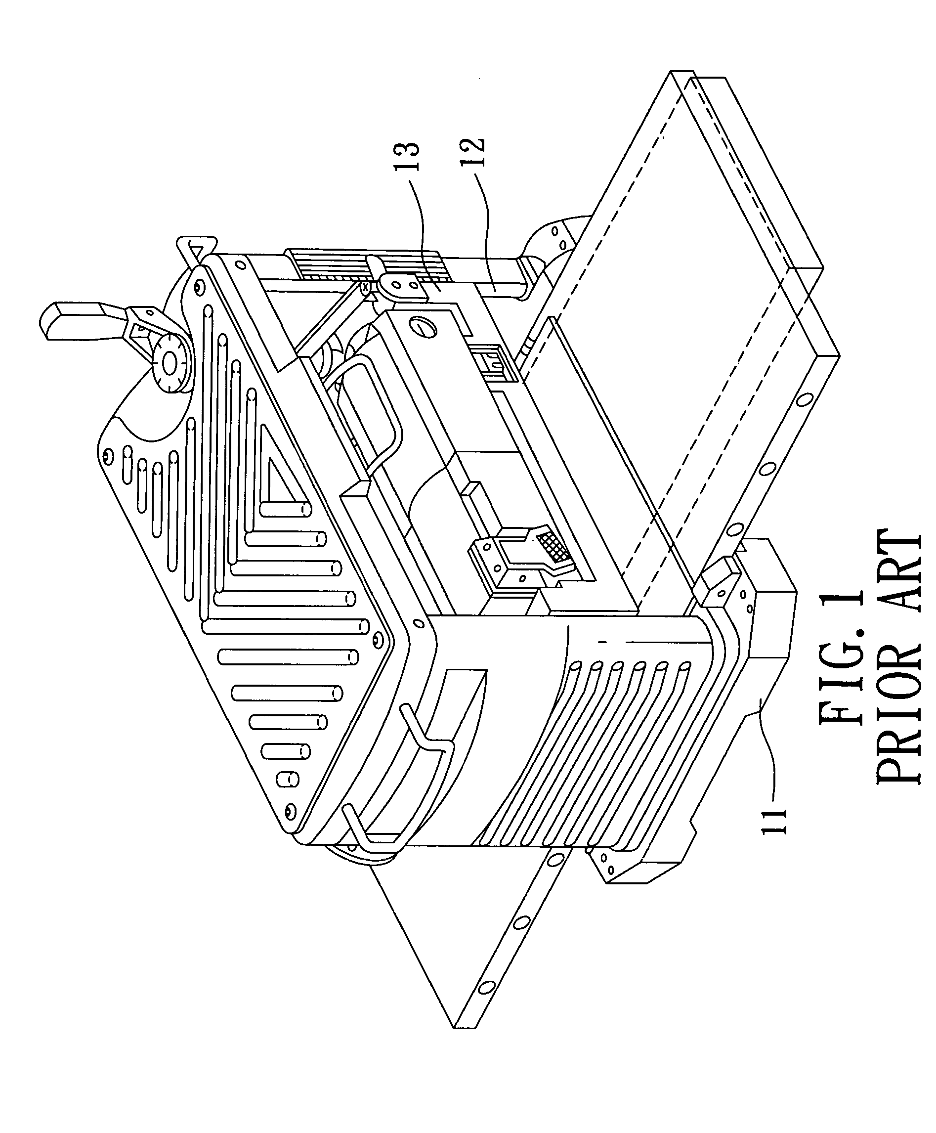
CROSS-REFERENCE TO RELATED APPLICATION[0001]This application claims priority of Taiwanese Application No. 093203293, filed on Mar. 5, 2004.BACKGROUND OF THE INVENTION[0002]1. Field of the Invention[0003]This invention relates to a rotary cutter for a wood planing machine, more particularly to a rotary cutter including a pair of blade-aligning members for aligning blades on a shaft.[0004]2. Description of the Related Art[0005]FIGS. 1 to 3 illustrate a conventional wood planing machine that includes a base 11, posts 12 standing upright from the base 11, a cutter carriage 13 mounted movably on the posts 12, and a rotary cutter 14 mounted rotatably on the cutter carriage 13. The rotary cutter 14 includes a shaft 15 that is formed with a plurality of first recesses 153, and a plurality of blades 16, each of which is mounted securely on the shaft 15 and each of which is disposed in a respective one of the first recesses 153. A pair of urging members 154 are disposed in each of the first r...

Claims


Application Information

Patent Timeline
Patent Type & Authority Patents(United States)
IPC IPC(8): B27C1/02B26D1/12B27G13/02B27C5/02A01D34/00B27C1/14B27G13/04
CPCB27G13/04Y10T407/1936Y10T83/9464
Inventor LIU, CHIN YUAN
Owner SHINMAX IND
Learn More